
Shigley's Mechanical Engineering Design (McGraw-Hill Series in Mechanical Engineering)
10th Edition
ISBN: 9780073398204
Author: Richard G Budynas, Keith J Nisbett
Publisher: McGraw-Hill Education
expand_more
expand_more
format_list_bulleted
Concept explainers
Videos
Textbook Question
Chapter 8, Problem 59P
A 1-in-diameter hot-rolled AISI 1144 steel rod is hot-formed into an eyebolt similar to that shown in the figure for Prob. 3–122, with an inner 3-in-diameter eye. The threads are 1 in-12 UNF and are die-cut.
(a) For a repeatedly applied load collinear with the thread axis, using the Gerber criterion, is fatigue failure more likely in the thread or in the eye?
(b) What can be done to strengthen the bolt at the weaker location?
(c) If the factor of safety guarding against a fatigue failure is nf = 2, what repeatedly applied load can be applied to the eye?
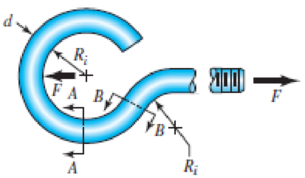
Problem 3–122
Expert Solution & Answer
Want to see the full answer?
Check out a sample textbook solution
Students have asked these similar questions
The figure below shows a boat propeller mounted on a drive shaft with a 7 mm diameter (d) cylindrical drive pin inserted through the hub
and the shaft. The drive shaft diameter, D, inside the hub is 69 mm. The pin is made from AISI 1020 cold rolled steel, which has a yield stress
of 427 MPa and an ultimate stress of 621 MPa. If the drive pin is subjected to an overload (e.g. strikes a log), calculate the torque (Nm)
required to shear the pin.
Note: Assume that the max shear stress of the pin material is approximately equal 82% of the ultimate tensile stress.
Do not include units in your answer.
Pin
F
Hub
Drive
pin
Shaft
Drive
shaft
F
Shear
planes
Hub
Answer:
A solid round bar with diameter of 2 in has a groove cut to a diameter of 1.8 in, with a radius of 0.1 in. The bar is not
rotating. The bar is loaded with a repeated bending load that causes the bending moment at the groove to fluctuate
between 0 and 25 000 lbf in. The bar is hot-rolled AISI 1095, but the groove has been machined. Determine the factor
of safety for fatigue based on infinite life and the factor of safety for yielding.
Plars &
.
A rectangular bar is cut from an AISI 1020 cold-drawn steel flat. The bar is 1.5 in wide by 3/8 in thick and has a 0.3-in-dia.
hole drilled through the center as depicted in Table A-15-1. The bar is concentrically loaded in push-pull fatigue by axial
forces Fa uniformly distributed across the width, Using a design factor of nd 2. estimate the largest force Fa that can be
applied ignoring column action.
What is the largest force that can be applied to the part?
The largest force that can be applied is 2.231 kips.
Chapter 8 Solutions
Shigley's Mechanical Engineering Design (McGraw-Hill Series in Mechanical Engineering)
Ch. 8 - A power screw is 25 mm in diameter and has a...Ch. 8 - Using the information in the footnote of Table...Ch. 8 - Show that for zero collar friction the efficiency...Ch. 8 - A single-threaded power screw is 25 mm in diameter...Ch. 8 - The machine shown in the figure can be used for a...Ch. 8 - The press shown for Prob. 8-5 has a rated load of...Ch. 8 - For the screw clamp shown, a force is applied at...Ch. 8 - The C clamp shown in the figure for Prob. 8-7 uses...Ch. 8 - Find the power required to drive a 1.5-in power...Ch. 8 - A single square-thread power screw has an input...
Ch. 8 - Prob. 11PCh. 8 - An M14 2 hex-head bolt with a nut is used to...Ch. 8 - Prob. 13PCh. 8 - A 2-in steel plate and a 1-in cast-iron plate are...Ch. 8 - Repeat Prob. 8-14 with the addition of one 12 N...Ch. 8 - A 2-in steel plate and a 1-in cast-iron plate are...Ch. 8 - Two identical aluminum plates are each 2 in thick,...Ch. 8 - Prob. 18PCh. 8 - A 30-mm thick AISI 1020 steel plate is sandwiched...Ch. 8 - Prob. 20PCh. 8 - Prob. 21PCh. 8 - Prob. 22PCh. 8 - A 2-in steel plate and a 1-in cast-iron plate are...Ch. 8 - An aluminum bracket with a 12-in thick flange is...Ch. 8 - An M14 2 hex-head bolt with a nut is used to...Ch. 8 - A 34 in-16 UNF series SAE grade 5 bolt has a 34-in...Ch. 8 - From your experience with Prob. 8-26, generalize...Ch. 8 - Prob. 28PCh. 8 - Prob. 29PCh. 8 - Prob. 30PCh. 8 - For a bolted assembly with eight bolts, the...Ch. 8 - Prob. 32PCh. 8 - 8-33 to 8-36 The figure illustrates the...Ch. 8 - 8-33 to 8-36 The figure illustrates the...Ch. 8 - 8-33 to 8-36 The figure illustrates the...Ch. 8 - 8-33 to 8-36 The figure illustrates the...Ch. 8 - Prob. 37PCh. 8 - Prob. 38PCh. 8 - 837 to 840 Repeat the requirements for the problem...Ch. 8 - Prob. 40PCh. 8 - 841 to 844 For the pressure vessel defined in the...Ch. 8 - Prob. 42PCh. 8 - Prob. 43PCh. 8 - Prob. 44PCh. 8 - Bolts distributed about a bolt circle are often...Ch. 8 - The figure shows a cast-iron bearing block that is...Ch. 8 - Prob. 47PCh. 8 - Prob. 48PCh. 8 - Prob. 49PCh. 8 - Prob. 50PCh. 8 - 851 to 854 For the pressure cylinder defined in...Ch. 8 - Prob. 52PCh. 8 - 851 to 854 For the pressure cylinder defined in...Ch. 8 - 851 to 854 For the pressure cylinder defined in...Ch. 8 - 855 to 858 For the pressure cylinder defined in...Ch. 8 - 855 to 858 For the pressure cylinder defined in...Ch. 8 - 855 to 858 For the pressure cylinder defined in...Ch. 8 - For the pressure cylinder defined in the problem...Ch. 8 - A 1-in-diameter hot-rolled AISI 1144 steel rod is...Ch. 8 - The section of the sealed joint shown in the...Ch. 8 - Prob. 61PCh. 8 - Prob. 62PCh. 8 - Prob. 63PCh. 8 - Prob. 64PCh. 8 - Using the Goodman fatigue criterion, repeat Prob....Ch. 8 - The figure shows a bolted lap joint that uses SAE...Ch. 8 - Prob. 67PCh. 8 - A bolted lap joint using ISO class 5.8 bolts and...Ch. 8 - Prob. 69PCh. 8 - The figure shows a connection that employs three...Ch. 8 - A beam is made up by bolting together two cold...Ch. 8 - Prob. 72PCh. 8 - Prob. 73PCh. 8 - Prob. 74PCh. 8 - A vertical channel 152 76 (see Table A7) has a...Ch. 8 - The cantilever bracket is bolted to a column with...Ch. 8 - Prob. 77PCh. 8 - The figure shows a welded fitting which has been...Ch. 8 - Prob. 79PCh. 8 - Prob. 80PCh. 8 - Prob. 81P
Knowledge Booster


Learn more about
Need a deep-dive on the concept behind this application? Look no further. Learn more about this topic, mechanical-engineering and related others by exploring similar questions and additional content below.Similar questions
- A stepped bar with a hole (see figure) has widths h = 2.4 in. and c = 1.6 in. The fillets have radii equal to 0.2 in. What is the diameter d max of the largest hole that can be drilled through the bar without reducing the load-carrying capacity?arrow_forwardSolve the preceding problem if the diameter is 480 mm, the pressure is 20 MPa, the yield stress in tension is 975 MPa, the yield stress in shear is 460 MPa, the factor of safety is 2,75, the modulus of elasticity is 210 GPa, Poissorfs ratio is 0.28, and the normal strain must not exceed 1190 x 10" . For part (b), assume that the tank thickness is 8 mm and the measured normal strain is 990 x 10~arrow_forwardThe figure shows a section of a large coupling. Each bolt in this joint is subjected to cyclic load fluctuating between 0 and 13 kN. The members are made from steel. The members have equal thicknesses and total length of members is L=37 mm. Each bolt is initially tightened carefully to 78% of proof load. The bolt is to be Metric grade 5.8 M12x1.75 (coarse-pitch series). The threads has been manufactured by rolling and reliability for bolts is 95%. Calculate the stiffness of the bolt (in kN/mm). Yanıt:arrow_forward
- A solid round bar with diameter of 50.800 mm has a groove cut to a diameter of 45.720 mm, with a radius of 2.540 mm. The bar is not rotating. The bar is loaded with a repeated bending load that causes the bending moment at the groove to fluctuate between 0 and 2825.000 N m. The bar is hot-rolled AISI 1095, but the groove has been machined. Determine the factor of safety for fatigue based on infinite life using the Goodman criterion, and the factor of safety for yielding.arrow_forwardProblem 2: F = 10 kip -10 in- -5 in- -5 in- d/5 R. R1 d/ 10 R. 1.4 d- R2 I in The shaft shown above rotates at 1200 RPM and supports a 10 kip load. The material of the shaft is 1095 hot-rolled steel and its surface is machined and then polished. Using a factor of safety of 1.6, specify the minimum value of diameter d for a life of 1,000 hours.arrow_forwardThe connecting rod in the figure is 10mm thick and manufactured from 8580M30 steel by cold drawing. The bar is threaded through the holes, loaded with fully variable load from the pins. Find the maximum load F to be applied to the part so that the part can have an indefinite life by looking at the appropriate figures for the stress concentrations that will occur due to the notch and drill hole.(Sut=600MPa,Sy=470Mpa)arrow_forward
- Solve the following problems as stated below. Draw the figure and FBD. PROBLEM A flanged bolt coupling consist of 9 steel bolts evenly spaced around a bolt circle 300 mm. in diameter and 6 bronze bolts on a concentric bplt circle 200 mm. in diameter. What are the sizes of bolts diameters for steel and bronze, if the torque applied is 6,000 N-m and without exceeding the stress of 60 MPa in the steel and 40 MPa for the bronze? The ratio of the bolt diameter dp / ds = 0.50. For steel, use Gs = 83 GPa and for bronze, Gp = 28 Gpa. R Rs Rbarrow_forwardSolve the following problems as stated below. Draw the figure and FBD. PROBLEM A flanged bolt coupling consist of 9 steel bolts evenly spaced around a bolt circle 300 mm. in diameter and 6 bronze bolts on a concentric bplt circle 200 mm. in diameter. What are the sizes of bolts diameters for steel and bronze, if the torque applied is 6,000 N-m and without exceeding the stress of 60 MPa in the steel and 40 MPa for the bronze? The ratio of the bolt diameter d, / ds = 0.50. For steel, use Gs = 83 GPa and for bronze, G, = 28 Gpa. %3D Rs Rparrow_forwardThe shaft is shown in Figure 3 is modified using the shaft from Question 2. Manufacturer selected as machined surface treatment for the shaft. It contains two fillets and one groove. The shaft rotates at 3000 řpm, whilst the imposed loads remain static. (a) Ifthe shaft is subjected to two-point load as shown below, F =10 kN, Calculate the factor of safety with respect to fatigue failure. (b) If the shaft is subjected to two-point load F= 10 kN while transmitting a power of P = 32 kW, Calculate the factor of safety with respect to fatigue failure. (L1 = 70 mm, L2 = 100 mm, L3 = 80 mm, La = 40 mm, Ls = 50 mm, L6 = 30 mm, Rj = 2 mm, R2 1 mm, R3= 4 mm, d = 24mm and D = 32mm,) 0.3F 0.7F LI Ls L. L6 ノ R1 R3 R2arrow_forward
- The figure shows a shaft mounted in bearings at A and D and having pulleys at B and C. The forces shown acting on the pulley surfaces represent the belt tensions. The shaft is to be made of AISI 1035 CD steel. The shaft is rotating at speed of 1000 rpm. Find the minimum factor of safety for fatigue based on infinite life. If the life is not infinite, estimate the number of cycles. Be sure to check for yielding. Take shaft diameter to be 1.5 inches.arrow_forwardA screw clamp similar to the one shown in the figure has a handle with diameter in made of cold-drawn AISI 1006 steel. The overall length is 3 in. The screw is in-14 UNC and is 5 in long, overall. Distance A is 2 in. The clamp will accommodate parts up to 4 in high. (a) What screw torque will cause the handle to bend permanently? (b) What clamping force will the answer to part (a) cause if the collar friction is neglected and if the thread friction is 0.075? ट Problem 8-7 B !!!!!!!arrow_forwardA screw clamp shown in the figure has a handle with diameter 5 mm made of cold-drawn AISI 1006 steel (table E18 - page 1195). The overall length of the hand is 75 mm. The screw is M 12 coarse (table 8-1) and is 145 mm long, overall. Distance A is 50 mm. The clamp will accommodate parts up to 105 mm high.a) What is the value of screw torque that causes the handle to bend permanently?b) If the collar friction is neglected and if the thread friction is 0.075, what is the screw force value that causes the handle to bend permanently?c) What is the value of clamping force, which will cause the screw to buckle?d) Are there any other stresses or possible failures to be checked?e) If yes, calculate them.arrow_forward
arrow_back_ios
SEE MORE QUESTIONS
arrow_forward_ios
Recommended textbooks for you
 Mechanics of Materials (MindTap Course List)Mechanical EngineeringISBN:9781337093347Author:Barry J. Goodno, James M. GerePublisher:Cengage Learning
Mechanics of Materials (MindTap Course List)
Mechanical Engineering
ISBN:9781337093347
Author:Barry J. Goodno, James M. Gere
Publisher:Cengage Learning
Casting Metal: the Basics; Author: Casting the Future;https://www.youtube.com/watch?v=2CIcvB72dmk;License: Standard youtube license