
Shigley's Mechanical Engineering Design (McGraw-Hill Series in Mechanical Engineering)
10th Edition
ISBN: 9780073398204
Author: Richard G Budynas, Keith J Nisbett
Publisher: McGraw-Hill Education
expand_more
expand_more
format_list_bulleted
Videos
Textbook Question
Chapter 8, Problem 26P
A
Problem 8-26
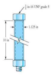
- (a) Determine the bolt stiffness, the tube stiffness, and the joint constant C.
- (b) When the one-third turn-of-nut is applied, what is the initial tension Fi in the bolt?
Expert Solution & Answer
Want to see the full answer?
Check out a sample textbook solution
Students have asked these similar questions
Two identical aluminum plates are each 3 in thick, and are compressed with one bolt and nut.
Washers are used under the head of the bolt and under the nut.
Washer properties: steel; ID = 0.531 in; OD = 1.062 in; thickness = 0.095 in
Nut properties: steel; height = 7/16 in
Bolt properties: 1/2 in-13 UNC grade 8
Plate properties: aluminum; E = 10.3 Mpsi; Su = 47 kpsi; Sy = 25 kpsi
(a) Determine a suitable length for the bolt, rounded up to the nearest 1/4 in.
(b) Determine the bolt stiffness.
(c) Determine the stiffness of the members.
1. For a bolted assembly with six bolts, the stiffness of each bolt is k, = 3 Mlbf/in and the stiffness of the
members is km = 12 Mlbf/in per bolt. An external load of 80 kips is applied to the entire joint. Assume
the load is equally distributed to all the bolts. It has been determined to use 1/2 in-13 UNC grade 8 bolts
with rolled threads. Assume a torque co-efficient of K = 0.2.
a. Determine the maximum bolt preload that can be applied without exceeding the proof strength of the
bolts.
b. Determine the minimum bolt preload that can be applied while avoiding joint separation.
c. Determine the value of torque in units of Ibf-ft that should be specified for preloading the bolts if it is
desired to preload to 75% of the proof load.
d. Determine the yielding factor of safety for part c). (based on proof strength)
10-23
Problem 10-23
Clamping fixture.
A holding fixture for a workpiece 37.5 mm thick at the clamp locations is being designed. The
detail of one of the clamps is shown in the figure. A spring is required to drive the clamp
upward when removing the workpiece with a starting force of 45 N. The clamp screw has an
M10 X 1.25 thread. Allow a diametral clearance of 1.25 mm between it and the uncompressed
spring. It is further specified that the free length of the spring should be Lo ≤ 48 mm, the solid
height L, 31.5 mm, and the safety factor when closed solid should be n, 1.2. Starting with
d = 2 mm, design a suitable helical coil compression spring for this fixture. For A227 HD
steel, wire diameters are available in 0.2-mm increments between 0.2 to 3.2 mm.
Clamp screw
Spherical washer
Slot
Workpiece
Clamp
Groove
Pin
Chapter 8 Solutions
Shigley's Mechanical Engineering Design (McGraw-Hill Series in Mechanical Engineering)
Ch. 8 - A power screw is 25 mm in diameter and has a...Ch. 8 - Using the information in the footnote of Table...Ch. 8 - Show that for zero collar friction the efficiency...Ch. 8 - A single-threaded power screw is 25 mm in diameter...Ch. 8 - The machine shown in the figure can be used for a...Ch. 8 - The press shown for Prob. 8-5 has a rated load of...Ch. 8 - For the screw clamp shown, a force is applied at...Ch. 8 - The C clamp shown in the figure for Prob. 8-7 uses...Ch. 8 - Find the power required to drive a 1.5-in power...Ch. 8 - A single square-thread power screw has an input...
Ch. 8 - Prob. 11PCh. 8 - An M14 2 hex-head bolt with a nut is used to...Ch. 8 - Prob. 13PCh. 8 - A 2-in steel plate and a 1-in cast-iron plate are...Ch. 8 - Repeat Prob. 8-14 with the addition of one 12 N...Ch. 8 - A 2-in steel plate and a 1-in cast-iron plate are...Ch. 8 - Two identical aluminum plates are each 2 in thick,...Ch. 8 - Prob. 18PCh. 8 - A 30-mm thick AISI 1020 steel plate is sandwiched...Ch. 8 - Prob. 20PCh. 8 - Prob. 21PCh. 8 - Prob. 22PCh. 8 - A 2-in steel plate and a 1-in cast-iron plate are...Ch. 8 - An aluminum bracket with a 12-in thick flange is...Ch. 8 - An M14 2 hex-head bolt with a nut is used to...Ch. 8 - A 34 in-16 UNF series SAE grade 5 bolt has a 34-in...Ch. 8 - From your experience with Prob. 8-26, generalize...Ch. 8 - Prob. 28PCh. 8 - Prob. 29PCh. 8 - Prob. 30PCh. 8 - For a bolted assembly with eight bolts, the...Ch. 8 - Prob. 32PCh. 8 - 8-33 to 8-36 The figure illustrates the...Ch. 8 - 8-33 to 8-36 The figure illustrates the...Ch. 8 - 8-33 to 8-36 The figure illustrates the...Ch. 8 - 8-33 to 8-36 The figure illustrates the...Ch. 8 - Prob. 37PCh. 8 - Prob. 38PCh. 8 - 837 to 840 Repeat the requirements for the problem...Ch. 8 - Prob. 40PCh. 8 - 841 to 844 For the pressure vessel defined in the...Ch. 8 - Prob. 42PCh. 8 - Prob. 43PCh. 8 - Prob. 44PCh. 8 - Bolts distributed about a bolt circle are often...Ch. 8 - The figure shows a cast-iron bearing block that is...Ch. 8 - Prob. 47PCh. 8 - Prob. 48PCh. 8 - Prob. 49PCh. 8 - Prob. 50PCh. 8 - 851 to 854 For the pressure cylinder defined in...Ch. 8 - Prob. 52PCh. 8 - 851 to 854 For the pressure cylinder defined in...Ch. 8 - 851 to 854 For the pressure cylinder defined in...Ch. 8 - 855 to 858 For the pressure cylinder defined in...Ch. 8 - 855 to 858 For the pressure cylinder defined in...Ch. 8 - 855 to 858 For the pressure cylinder defined in...Ch. 8 - For the pressure cylinder defined in the problem...Ch. 8 - A 1-in-diameter hot-rolled AISI 1144 steel rod is...Ch. 8 - The section of the sealed joint shown in the...Ch. 8 - Prob. 61PCh. 8 - Prob. 62PCh. 8 - Prob. 63PCh. 8 - Prob. 64PCh. 8 - Using the Goodman fatigue criterion, repeat Prob....Ch. 8 - The figure shows a bolted lap joint that uses SAE...Ch. 8 - Prob. 67PCh. 8 - A bolted lap joint using ISO class 5.8 bolts and...Ch. 8 - Prob. 69PCh. 8 - The figure shows a connection that employs three...Ch. 8 - A beam is made up by bolting together two cold...Ch. 8 - Prob. 72PCh. 8 - Prob. 73PCh. 8 - Prob. 74PCh. 8 - A vertical channel 152 76 (see Table A7) has a...Ch. 8 - The cantilever bracket is bolted to a column with...Ch. 8 - Prob. 77PCh. 8 - The figure shows a welded fitting which has been...Ch. 8 - Prob. 79PCh. 8 - Prob. 80PCh. 8 - Prob. 81P
Knowledge Booster


Learn more about
Need a deep-dive on the concept behind this application? Look no further. Learn more about this topic, mechanical-engineering and related others by exploring similar questions and additional content below.Similar questions
- Based on the figure If spring A is compressed (L / 8) Which shape is correct? 1 or 2 ?arrow_forward34 in 3. The following data apply to the C-clamp: a. The screw is ACME with ¾" Diameter b. Coefficient of thread friction = 0.12 c. Coefficient of collar friction = 0.23 d. Mean collar radius = 0.55 in. e. Max. clamping force = 1000 lb Determine: The tightening torque The operator force at the end of the handle (Note: Use table 8-3 to determine the screw pitch (p))arrow_forwardRequired information For a bolted assembly with six bolts, the stiffness of each bolt is kb 2 Mibf/in and the stiffness of the members is km = 13 Mlbf/in per bolt. An external load of 80 kips is applied to the entire joint. Assume the load is equally distributed to all the bolts. It has been determined to use 1/2 in-13 UNC grade 8 bolts with rolled threads. It is desired to find the range of torque that a mechanic could apply to initially preload the bolts without expecting failure once the joint is loaded. Assume a torque coefficient of K = 0.2. NOTE: This is a multi-part question. Once an answer is submitted, you will be unable to return to this part. Determine the maximum bolt preload that can be applied without exceeding the proof strength of the bolts once the load is applied. The maximum bolt preload that can be applied is Ibf.arrow_forward
- RB&W11 recommends turn-of-nut from snug fit to preload as follows: 1/3 turn for bolt grips of 1-4 diameters, 1/2 turn for bolt grips 4-8 diameters, and 2/3 turn for grips of 8-12 diameters. These recommendations are for structural steel fabrication (permanent joints), producing preloads of 100 percent of proof strength and beyond. Machinery fabricators with fatigue loadings and possible joint disassembly have much smaller turns-of-nut. The RB&W recommendation enters the nonlinear plastic deformation zone. The figure shows a cross section of a grade 25 cast-iron pressure vessel, with a torque factor K of 0.09. Use Eq. (8-27) to estimate the torque necessary to establish the desired preload given that preload F;= 14.4 kip, bolt stiffness kb = 5.21 x 10⁶ lbf/in, number of threads N=11, and material stiffness km = 8.95 × 10⁶ lbf/in. in-11 UNCX 2 in grade 5 finished hex head bolt in in 162 No. 25 CI Determine the torque necessary to establish the desired preload and the turn of the nut in…arrow_forwardTwo plates are clamped by a 3/4-10 UNC SAE Grade 5 bolt and regular nut with a 3/4-W plain washer as shown in figure. Top plate is made of grey cast iron and bottom plate is steel. An axial force of 12kN is acted upon the joint. Round off the length of the bolt to nearest 1/4in. Assume bolts are preloaded to 75% of proof load. 1. Determine the bolt stiffness kb. 2. Determine the member stiffness km. 3. Determine the yielding factor of safety of the bolt. 4. Determine the load factor for the bolt. 5. Determine the load factor guarding against joint separation. 1.25 in 1.00 inarrow_forwardRB&W¹1 recommends turn-of-nut from snug fit to preload as follows: 1/3 turn for bolt grips of 1-4 diameters, 1/2 turn for bolt grips 4-8 diameters, and 2/3 turn for grips of 8-12 diameters. These recommendations are for structural steel fabrication (permanent joints), producing preloads of 100 percent of proof strength and beyond. Machinery fabricators with fatigue loadings and possible joint disassembly have much smaller turns-of-nut. The RB&W recommendation enters the nonlinear plastic deformation zone. The figure shows a cross section of a grade 25 cast-iron pressure vessel, with a torque factor K of 0.09. Use Eq. (8-27) to estimate the torque necessary to establish the desired preload given that preload F; = 14.4 kip, bolt stiffness kb = 5.21 x 10⁶ lbf/in, number of threads N = 11, and material stiffness km = 8.95 × 10⁶ lbf/in. in-11 UNCX 2+ in grade 5 finished hex head bolt in No. 25 CI Determine the torque necessary to establish the desired preload and the turn of the nut in…arrow_forward
- The figure illustrates the nonpermanent connection of a steel cylinder head to a grade 30 cast-iron pressure vessel using 73 bolts. A confined gasket seal has an effective sealing diameter D of 0.9 m. The cylinder pressure is cycled between a minimum pressure of zero and a maximum pressure pg of 535 kPa. For the specifications given in the table for the specific problem assigned, select a suitable bolt length from the preferred sizes. Use Table A-17 for calculation purposes. Parameter Value Head thickness, A Cylinder thickness, B Internal diameter of the cylinder, C Gasket sealing diameter, D Bolt circle diameter, E Outer diameter of the cylinder head, 16 mm 25 mm 0.8 m 0.9 m 1.0 m 1.1 m F Bolt grade ISO 10.9 Bolt diameter, d 10 mm NOTE: This is a multi-part question. Once an answer is submitted, you will be unable to return to this part. Find a suitable bolt length. Then, determine the bolt stiffness, material stiffness, and stiffness constant of the joint. The bolt length is 50 mm.…arrow_forwardIn the Bolted Connection shown, find the following by ASD.Specifications:M20 Bolts in standard holes.Nominal hole diameter = 22mmEffective Hole diameter = nominal hole diameter + 2 mmA325 steel boltAssume thread in shear planeFv = 372 MPaProperties of Angle Bar< 125 x 125 x 13 mmA = 3065 mm²x = 36.3 mmy = 36.3 mmFy = 248 MPa , Fu = 410 MPa 1. Considering shearing in bolts, what is the allowable force P (kN) that the connection can handle if allowable shearing stress in bolts is Fv/2 a. 257.61 b. 390.25 c. 233.73 d. 309.25 2. Considering yielding of angle bar, what is the allowable force P that the connection can handle if allowable yielding stress in gross area of angle bar is Fy/1.67 a. 201.25 b. 455.16 c. 403.03 d. 509.25 3. For angle bars used as bolted tension element connected to another element only on one leg, the effective area Ae = UAn. Where: An = Net area, U = Shear lag factor = 1 –…arrow_forwardIn the Bolted Connection shown, find the following by ASD.Specifications:M20 Bolts in standard holes. Nominal hole diameter = 22mmEffective Hole diameter = nominal hole diameter + 2 mmA325 steel boltAssume thread in shear planeFv = 372 MPaProperties of Angle Bar< 125 x 125 x 13 mmA = 3065 mm²x = 36.3 mmy = 36.3 mmFy = 248 MPa , Fu = 410 MPa 1. For angle bars used as bolted tension element connected to another element only on one leg, the effective area Ae = UAn. Where: An = Net area, U = Shear lag factor = 1 – x/L, L= center to center longitudinal distance of extremely located fasteners, X= distance from centroid of angle bar to surface of contact of joined elements. What is the shear lag factor of our angular bar? a. 0.454 b. 0.9 c. 0.838 d. 0.869 2. Considering RUPTURE of angle bar, what is the allowable force P that the connection can handle if allowable RUPTURE stress in net area of angle bar is Fu/2 a. 463.83 kN…arrow_forward
- 4) An electric motor purchased by your employer surprisingly arrived without a keyway in the shaft. The motor has power rating of 7.5kW & 1,800rpm & has a shaft of 17mm. It will be used to drive a centrifugal pump using cast iron sheave. Design the square key to be used in the assembly based on maximum bearing & shearing stresses of 580MPa & 370MPa, respectively, and factor of safety of 5.arrow_forwardA bolted joint is to have a grip consisting of two 14-mm steel plates and one 14R metric plain washer to fit under the head of the M14 x 2 hex-head bolt, 50 mm long. (Hint: Look up table A-31 and A-33 in the textbook of Shigley's Mechanical Engineering Design, 8th Edition) (a) What is the length of the thread LT for this diameter metric coarse-pitch series bolt? (b) What is the length of the grip l? (c) What is the height H of the nut? (d) Is the bolt long enough? If not, round to the next larger preferred length. (e) What is the length of the shank and the threaded portions of the bolt within the grip?arrow_forwardFor nut M16, F(=10N) is the force acted on the wrench, if the length L=15d,tightening torque coefficient K=0.2. Find: (1) The tightening torque T; (2) Preload Qp of this bolt. L=15d Problem 1) Figurearrow_forward
arrow_back_ios
SEE MORE QUESTIONS
arrow_forward_ios
Recommended textbooks for you
 Elements Of ElectromagneticsMechanical EngineeringISBN:9780190698614Author:Sadiku, Matthew N. O.Publisher:Oxford University Press
 Mechanics of Materials (10th Edition)Mechanical EngineeringISBN:9780134319650Author:Russell C. HibbelerPublisher:PEARSON
 Thermodynamics: An Engineering ApproachMechanical EngineeringISBN:9781259822674Author:Yunus A. Cengel Dr., Michael A. BolesPublisher:McGraw-Hill Education
 Control Systems EngineeringMechanical EngineeringISBN:9781118170519Author:Norman S. NisePublisher:WILEY
 Mechanics of Materials (MindTap Course List)Mechanical EngineeringISBN:9781337093347Author:Barry J. Goodno, James M. GerePublisher:Cengage Learning
 Engineering Mechanics: StaticsMechanical EngineeringISBN:9781118807330Author:James L. Meriam, L. G. Kraige, J. N. BoltonPublisher:WILEY
Elements Of Electromagnetics
Mechanical Engineering
ISBN:9780190698614
Author:Sadiku, Matthew N. O.
Publisher:Oxford University Press
Mechanics of Materials (10th Edition)
Mechanical Engineering
ISBN:9780134319650
Author:Russell C. Hibbeler
Publisher:PEARSON
Thermodynamics: An Engineering Approach
Mechanical Engineering
ISBN:9781259822674
Author:Yunus A. Cengel Dr., Michael A. Boles
Publisher:McGraw-Hill Education
Control Systems Engineering
Mechanical Engineering
ISBN:9781118170519
Author:Norman S. Nise
Publisher:WILEY
Mechanics of Materials (MindTap Course List)
Mechanical Engineering
ISBN:9781337093347
Author:Barry J. Goodno, James M. Gere
Publisher:Cengage Learning
Engineering Mechanics: Statics
Mechanical Engineering
ISBN:9781118807330
Author:James L. Meriam, L. G. Kraige, J. N. Bolton
Publisher:WILEY
Mechanical SPRING DESIGN Strategy and Restrictions in Under 15 Minutes!; Author: Less Boring Lectures;https://www.youtube.com/watch?v=dsWQrzfQt3s;License: Standard Youtube License