
Concept explainers
Videos
8–55 to
8–58 For the pressure cylinder defined in the problem specified in the table, the gas pressure is cycled between pg and pg/2. Determine the fatigue factor of safety for the bolts using the Goodman criterion.
| Problem Number | Originating Problem Number |
| 8–55 | 8–33 |
| 8–56 | 8–34 |
| 8–57 | 8–35 |
| 8–58 | 8–36 |
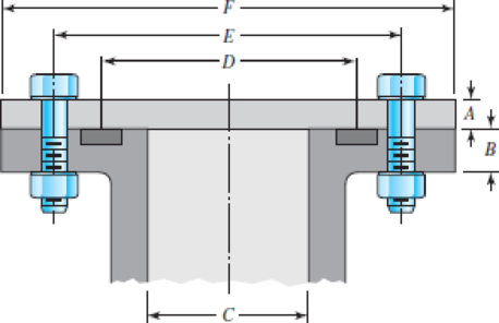
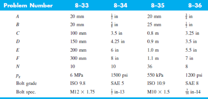
8–33 to
8–36 The figure illustrates the non-permanent connection of a steel cylinder head to a grade 30 castiron pressure vessel using N bolts. A confined gasket seal has an effective sealing diameter D. The cylinder stores gas at a maximum pressure pg. For the specifications given in the table for the specific problem assigned, select a suitable bolt length from the preferred sizes in Table A–17, then determine the yielding factor of safety np, the load factor nL, and the joint separation factor n0.
11Russell, Burdsall & Ward, Inc., Metal Forming Specialists, Mentor, Ohio.
Problems 8–33 to 8–36
Want to see the full answer?
Check out a sample textbook solution
Chapter 8 Solutions
Shigley's Mechanical Engineering Design (McGraw-Hill Series in Mechanical Engineering)


- A 1-in-diameter solid round bar has a groove 0.1-in deep with a 0.1-in radius machined into it. The bar is made of AISI 1020 CD steel and is subjected to a purely reversing torque of 1800 lb-in. For the S-N diagram of this material, let f=0.9. Estimate the number of cycles to failure. If the bar is also placed in an environment with a temperature of 750 F, estimate the number of cycles to failurearrow_forwardRequired information The shaft shown in the figure is machined from AISI 1040 CD steel. The shaft rotates at 1600 rpm and is supported in rolling bearings at A and B. The applied forces are F₁ = 800 lbf and F2=1200 lbf. Determine the minimum fatigue factor of safety based on achieving infinite life. If infinite life is not predicted, estimate the number of cycles to failure. Also check for yielding -10 in- -10 is -fim All Gillets in R. What are the values of the theoretical stress-concentration factor, the notch sensitivity, and the fatigue stress-concentration factor? The value of the theoretical stress concentration-factor is The value of the notch sensitivity is. The value of the fatigue stress concentration-factor is [arrow_forwardQ1 (a): A cold-drawn solid steel shaft is driven at N=295 RPM carries two gears D and E, as shown in the figure. Gear D has an input power of Pp= 11 kW, while gear E gives an equal output power. For a factor of safety of n=2.2, design the shaft according to the following failure criteria: Assume Sy= 291 MPa, Sut= 597 MPa, Kf=1.3, K=1.4 15 kg 15 kg A E 0.4 m e 0.6 m 0.4 m Calculate endurance limit, Se, in MPa units assuming all the Marin factors are unity. Enter only numeric value without units. Assume k=0.77 and the shaft is operating at room temperature of 70°F with 50% reliability.arrow_forward
- Example 8-4 in SI Units. • Q-2 Figure gives the cross section of a grade 25 cast-iron pressure vessel. A total of N bolts are to be used to resist a M16 x 2 x 60 mm class 5.8 separating force of 36 kip (160.2 kN). • (a) Determine k,, Kmy and C. • (b) Find the number of bolts required for a load factor of 2 where the bolts may be reused when the joint is taken apart. hexagonal head bolt No: 25 CI 20 mm 20 mm • (c) With the number of bolts obtained in part (b), determine the realized load factor for overload, the yielding factor of safety, and the load factor for joint separation. H = 14.8 mmarrow_forwardRequired information The bolted connection shown in the figure is subjected to a tensile shear load of 90 kN. The bolts are ISO class 5.8, and the material is cold-drawn AISI 1015 steel. Assume the bolt threads do not extend into the joint. Find the factor of safety of the connection for all possible modes of failure. Give the overall joint factor of safety. Given: t = 15 mm and t2 = 25 mm. NOTE: This is a multi-part question. Once an answer is submitted, you will be unable to return to this part. 35 60 60 - 35 t1 M20 x 2.5 35 35 + t2 Find the overall joint factor of safety. The overall joint factor of safety noverall isarrow_forward8-75 A vertical channel 152 X 76 (see Table A–7) has a cantilever beam bolted to it as shown. The channel is hot-rolled AISI 1006 steel. The bar is of hot-rolled AISI 1015 steel. The shoulder bolts are M10 × 1.5 ISO 5.8. Assume the bolt threads do not extend into the joint. For a design factor of 2.0, find the safe force F that can be applied to the cantilever. 8T-8 12 Problem 8-75 in millimeters. 50 -50→-50→261! 125 000arrow_forward
- The cantilever bracket is bolted to a column with three M12x1.75 ISO 5.8 bolts. The bracket is made from AISI 1020 hot-rolled steel. Find the factors of safety for the following failure modes: shear of bolts, bearing of bolts, bearing of bracket, and bending of bracket. Lazima 36 36 Holes for M12x 1.75 bolts 8 mm thick 200- 12 ANarrow_forwardQ1 (b): A cold-drawn solid steel shaft is driven at N=287 RPM carries two gears D andE, as shown in the figure. Gear D has an input power of Pp= 9 kW, while gear E gives an equal output power. For a factor of safety of n=2.5, design the shaft according to the following failure criteria: Assume Sy 309 MPa, Sut= 598 MPa, K=1.4, Ks =1.4 15 kg 15 kg D 0.4 m e 0.6 m 0.4 m - Calculate the mean torque, Tm in N.m units upto 4 digits after decimal. Enter only numeric value without units. Assume k = 0.81 and the shaft is operating at room temperature of 70°F with 50% reliability.arrow_forwardThe figure shows a section of a large coupling. Each bolt in this joint is subjected to cyclic load fluctuating between 0 and 13 kN. The members are made from steel. The members have equal thicknesses and total length of members is L=37 mm. Each bolt is initially tightened carefully to 78% of proof load. The bolt is to be Metric grade 5.8 M12x1.75 (coarse-pitch series). The threads has been manufactured by rolling and reliability for bolts is 95%. Calculate the stiffness of the bolt (in kN/mm). Yanıt:arrow_forward
- Two plates are clamped by a 3/4-10 UNC SAE Grade 5 bolt and regular nut with a 3/4-W plain washer as shown in figure. Top plate is made of grey cast iron and bottom plate is steel. An axial force of 12kN is acted upon the joint. Round off the length of the bolt to nearest 1/4in. Assume bolts are preloaded to 75% of proof load. 1. Determine the bolt stiffness kb. 2. Determine the member stiffness km. 3. Determine the yielding factor of safety of the bolt. 4. Determine the load factor for the bolt. 5. Determine the load factor guarding against joint separation. 1.25 in 1.00 inarrow_forward5-63 The figure shows a shaft mounted in bearings at A and D and having pulleys at B and C. The forces shown acting on the pulley surfaces represent the belt tensions. The shaft is to be made of AISI 1035 CD steel. Using a conservative failure theory with a design factor of 2, determine the minimum shaft diameter to avoid yielding. f-in R 300 Ibf 50 lbf 59 Ibf 392 lbf D Problem 5-63 C 6 in 8-in D. 8 in B 8 inarrow_forwardThe figure shows a schematic drawing of a vehicular jack that is to be designed to support a maximum mass of 300 kg based on the use of a design factor na = 3.50. The opposite-handed threads on the two ends of the screw are cut to allow the link angle 0 to vary from 15 to 70°. The links are to be machined from AISI 1010 hot-rolled steel bars. Each of the four links is to consist of two bars, one on each side of the central bearings. The bars are to be 350 mm long and have a bar width of w = 30 mm. The pinned ends are to be designed to secure an end-condition constant of at least C = 1.4 for out-of-plane buckling. Find a suitable preferred thickness and the resulting factor of safety for this thickness. W 華 warrow_forward
 Mechanics of Materials (MindTap Course List)Mechanical EngineeringISBN:9781337093347Author:Barry J. Goodno, James M. GerePublisher:Cengage Learning