
Concept explainers
Videos
For the pressure cylinder defined in the problem specified in the table, the gas pressure is cycled between pg and pg/2. Determine the fatigue factor of safety for the bolts using the Goodman criterion.
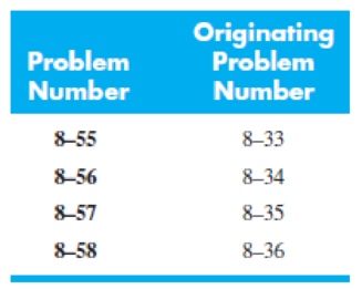
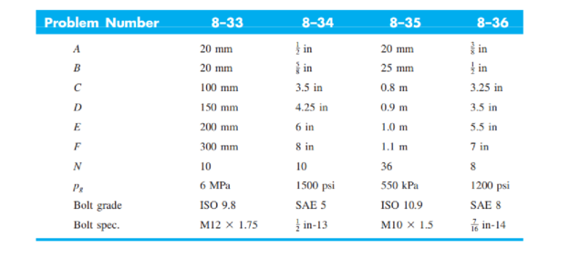
The figure illustrates the non-permanent connection of a steel cylinder head to a grade 30 castiron pressure vessel using N bolts. A confined gasket seal has an effective sealing diameter D. The cylinder stores gas at a maximum pressure pg. For the specifications given in the table for the specific problem assigned, select a suitable bolt length from the preferred sizes in Table A–17, then determine the yielding factor of safety np, the load factor nL, and the joint separation factor n0.
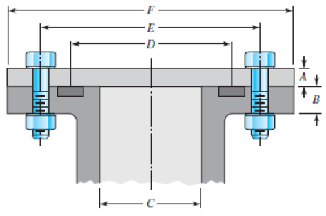
Problems 8–33 to 8–36
Want to see the full answer?
Check out a sample textbook solution
Chapter 8 Solutions
Shigley's Mechanical Engineering Design (McGraw-Hill Series in Mechanical Engineering)


- The figure illustrates the non-permanent connection of a steel cylinder head to a grade 30 cast- 8-35 iron pressure vessel usarrow_forwardAs shown in figure below, two plates are clamped by washer-faced 2 in-20 UNF SAE grade 5 bolts each with a standard 2 N steel plain washer. The top plate is steel and the bottom pplate is gray cast iron. If a total of 8 bolts where used to close 1 feet diameter pipe which applied at maximum pressure of 150 psi. Calculate the static and fatigue safety factor of this joint. Used Goodman theory for tha fatigue safety 1/2 factor. 3/4arrow_forwardDesign and draw a neat sketch of a cast iron protective type flange coupling to transmit “P” kW at “N” rpm. from a turbine generating n electric motor to a compressor. The service factor may be assumed as 1.35. The following permissible stress may be used: Shear stress for shaft, bolt and key material = 40 MPaCrushing stress for bolt and key = 80 MPaShear stress for cast iron = 8 MpaSpeed N in Rpm = 500Power P in kN = 15arrow_forward
- A link in a mechanism is to be subjected to a tensile force that varies from 3500 to 500 N in acyclical fashion as the mechanism runs. It has been decided to use AISI 1040 cold-drawn steel.Complete the design of the link, specifying a suitable cross-sectional shape and dimensions.5. Specify the required length of no. 60 chain to mount on sprockets having 15 and 50 teeth with acenter distance of no more than 36 in.arrow_forwardQ(1) :A helical compression spring is to be cycled between 150 lbf and 300 lbf with a 1-in stroke.The number of cycles is low, so fatigue is not an issue. The coil must fit in a 2.1-in diameter hole with a 0.1-in clearance all the way around the spring. Use unpeened oil tempered wire with squared and ground ends. (CLO1) (i) Determine a suitable wire diameter, using a spring index of C=7.(ii) Determine a suitable mean coil diameter.(iii) Determine the necessary spring constant.(iv) Determine a suitable total number of coils.(v) Determine the necessary free length so that if the spring were compressed to its solid length, there would be no yielding.arrow_forward4. A plate clutch has three discs on the driving shaft and two discs on the driven shaft, providing four pairs of contact surfaces. The outside diameter of the contact surfaces is 240 mm and inside diameter 120 mm. Assuming uniform pressure and f = 0.3, find the total spring load pressing the plates to transmit 25 kW at 1575 rpm. If there are 6 springs each of the contact surfaces has worn away by 1.25 mm, find the maximum power that can be transmitted, assuming uniform wear.arrow_forward
- Problem Set – Temperature Change 1. A steel tire has a dimensions indicated in the figure below. At 78 degrees Celsius, the said tire was fit into a 1.8m to an engine wheel with 24 degrees Celsius. Calculate the contact pressure between the tire and the wheel after fitting together due to colling of 24 degrees Celsius. The coefficient of expansion due to temperature of the tire is 12.3 micrometer/ m- degrees Celsius and Modulus of Elasticity is EN GPa. | 12 mm | 200 mm 900mm wide steel tire- 12 mm Note: Neglect the deformation of the wheel due to the pressure of the tire Fn- 100arrow_forwardProblem 4: A helical compression spring is to be cycled between 150 lbf and 300 lbf with a 1-in stroke. The number of cycles is low, so fatigue is not an issue. The coil must fit in a 2.1-in diameter hole with a 0.1-in clearance all the way around the spring. Use unpeened music wire with squared and ground ends. (a) Determine a suitable wire diameter, using a spring index of C = 7. (b) Determine a suitable mean coil diameter. (c) Determine the necessary spring constant. (d) Determine a suitable total number of coils. (e) Determine the necessary free length so that if the spring were compressed to its solid length, there would be no yieldingarrow_forwardA helical compression spring has a scale of 400 lbs/inch, an inside diameter of 2.5 inches, a free length of 8 inches and with squared and ground ends. Material is to be chrome vanadium steel. For a load P of 750 lbs and for the average service Determine the standard size wire diameter Determine the number of active coils Determine the solid height Determine the stress at solid heightarrow_forward
- Example 8-4 in SI Units. • Q-2 Figure gives the cross section of a grade 25 cast-iron pressure vessel. A total of N bolts are to be used to resist a M16 x 2 x 60 mm class 5.8 separating force of 36 kip (160.2 kN). • (a) Determine k,, Kmy and C. • (b) Find the number of bolts required for a load factor of 2 where the bolts may be reused when the joint is taken apart. hexagonal head bolt No: 25 CI 20 mm 20 mm • (c) With the number of bolts obtained in part (b), determine the realized load factor for overload, the yielding factor of safety, and the load factor for joint separation. H = 14.8 mmarrow_forwardThe figure shows a schematic drawing of a vehicular jack that is to be designed to support a maximum mass of 300 kg based on the use of a design factor na = 3.50. The opposite-handed threads on the two ends of the screw are cut to allow the link angle 0 to vary from 15 to 70°. The links are to be machined from AISI 1010 hot-rolled steel bars. Each of the four links is to consist of two bars, one on each side of the central bearings. The bars are to be 350 mm long and have a bar width of w = 30 mm. The pinned ends are to be designed to secure an end-condition constant of at least C = 1.4 for out-of-plane buckling. Find a suitable preferred thickness and the resulting factor of safety for this thickness. W 華 warrow_forwardRequired information The bolted connection shown in the figure is subjected to a tensile shear load of 90 kN. The bolts are ISO class 5.8, and the material is cold-drawn AISI 1015 steel. Assume the bolt threads do not extend into the joint. Find the factor of safety of the connection for all possible modes of failure. Give the overall joint factor of safety. Given: t = 15 mm and t2 = 25 mm. NOTE: This is a multi-part question. Once an answer is submitted, you will be unable to return to this part. 35 60 60 - 35 t1 M20 x 2.5 35 35 + t2 Find the overall joint factor of safety. The overall joint factor of safety noverall isarrow_forward
 Mechanics of Materials (MindTap Course List)Mechanical EngineeringISBN:9781337093347Author:Barry J. Goodno, James M. GerePublisher:Cengage Learning