
Loose Leaf for Engineering Circuit Analysis Format: Loose-leaf
9th Edition
ISBN: 9781259989452
Author: Hayt
Publisher: Mcgraw Hill Publishers
expand_more
expand_more
format_list_bulleted
Concept explainers
Videos
Textbook Question
Chapter 7, Problem 72E
(a) Sketch the output function vout of the amplifier circuit in Fig. 7.29 over the range of 0 ≤ t ≤ 100 ms if vs is a 60 Hz sinusoidal source having a peak voltage of 400 mV, R1 is 1 kΩ, and Lf is 250 mH. (b) Verify your answer with an appropriate transient simulation, plotting both vs and vout. (Note the scales are very different, so if using LTspice, it may be clearer to use the Add Plot Pane under the Plot Settings menu, and plot one trace per pane.)
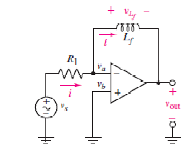
■ FIGURE 7.29
Expert Solution & Answer
Want to see the full answer?
Check out a sample textbook solution
Students have asked these similar questions
.l Asiacell LTE
e 7:09 PM
O 60%
2.pdf
Using inverting, non-inverting, Buffer, or Summer op_amps circuit to
design the following equation
Vo = 8 Vị
BJT Circuit Theory: I have this following circuit but its not producing the correct output. My input is a 0-3.3 V sine wave at 1 kHz. My output at the speaker should also be a 0-3.3 V sine wave, but its giving me the wrong output. How do I fix this circuit using transistor(s) ?
7.1 The CE amplifier below uses the collector resistor as the load resistor (ie. Rc = RL). Assume that Bac = Boc =
100. Determine the DC Q-point (ig. Icą and Væo), the voltage gain and the power gain.
+Vcc
+15 V
R
1.0 kN
RL
100 0
0.5 W
Vin
22 μF
REI
8.2 N
R2
330 N
500 mV pp
1.0 kHz
RE2
36 N
100 µF
Chapter 7 Solutions
Loose Leaf for Engineering Circuit Analysis Format: Loose-leaf
Ch. 7.1 - Determine the current flowing through a 5 mF...Ch. 7.1 - Prob. 2PCh. 7.1 - Prob. 3PCh. 7.2 - 7.4 The current through a 200 mH inductor is shown...Ch. 7.2 - The current waveform of Fig. 7.14a has equal rise...Ch. 7.2 - Prob. 6PCh. 7.2 - Let L = 25 mH for the inductor of Fig. 7.10. (a)...Ch. 7.3 - Find Ceq for the network of Fig. 7.23. FIGURE...Ch. 7.4 - If vC(t) = 4 cos 105t V in the circuit in Fig....Ch. 7.5 - Derive an expression for vout in terms of vs for...
Ch. 7.6 - Prob. 11PCh. 7 - Making use of the passive sign convention,...Ch. 7 - Prob. 2ECh. 7 - (a) If the voltage waveform depicted in Fig. 7.42...Ch. 7 - A capacitor is constructed from two brass plates,...Ch. 7 - Prob. 5ECh. 7 - Prob. 6ECh. 7 - Design a capacitor whose capacitance can be varied...Ch. 7 - Design a capacitor whose capacitance can be varied...Ch. 7 - Prob. 9ECh. 7 - Assuming the passive sign convention, sketch the...Ch. 7 - Prob. 11ECh. 7 - Prob. 12ECh. 7 - Prob. 13ECh. 7 - Calculate the power dissipated in the 40 resistor...Ch. 7 - Prob. 15ECh. 7 - Design a 30 nH inductor using 28 AWG solid soft...Ch. 7 - Prob. 17ECh. 7 - Prob. 18ECh. 7 - Prob. 19ECh. 7 - Prob. 20ECh. 7 - Calculate vL and iL for each of the circuits...Ch. 7 - The current waveform shown in Fig. 7.14 has a rise...Ch. 7 - Determine the inductor voltage which results from...Ch. 7 - Prob. 24ECh. 7 - The voltage across a 2 H inductor is given by vL =...Ch. 7 - Calculate the energy stored in a 1 nH inductor if...Ch. 7 - Determine the amount of energy stored in a 33 mH...Ch. 7 - Making the assumption that the circuits in Fig....Ch. 7 - Calculate the voltage labeled vx in Fig. 7.52,...Ch. 7 - Prob. 30ECh. 7 - Prob. 31ECh. 7 - Determine an equivalent inductance for the network...Ch. 7 - Using as many 1 nH inductors as you like, design...Ch. 7 - Compute the equivalent capacitance Ceq as labeled...Ch. 7 - Prob. 35ECh. 7 - Prob. 36ECh. 7 - Reduce the circuit depicted in Fig. 7.59 to as few...Ch. 7 - Refer to the network shown in Fig. 7.60 and find...Ch. 7 - Prob. 39ECh. 7 - Prob. 40ECh. 7 - Prob. 41ECh. 7 - Prob. 42ECh. 7 - Prob. 43ECh. 7 - Prob. 44ECh. 7 - Prob. 45ECh. 7 - Prob. 46ECh. 7 - Prob. 47ECh. 7 - Let vs = 100e80t V with no initial energy stored...Ch. 7 - Prob. 49ECh. 7 - Prob. 50ECh. 7 - Interchange the location of R1 and Cf in the...Ch. 7 - For the integrating amplifier circuit of Fig....Ch. 7 - Prob. 53ECh. 7 - For the circuit shown in Fig. 7.73, assume no...Ch. 7 - A new piece of equipment designed to make crystals...Ch. 7 - An altitude sensor on a weather balloon provides a...Ch. 7 - One problem satellites face is exposure to...Ch. 7 - The output of a velocity sensor attached to a...Ch. 7 - A floating sensor in a certain fuel tank is...Ch. 7 - (a) If Is = 3 sin t A, draw the exact dual of the...Ch. 7 - Draw the exact dual of the simple circuit shown in...Ch. 7 - (a) Draw the exact dual of the simple circuit...Ch. 7 - (a) Draw the exact dual of the simple circuit...Ch. 7 - Prob. 64ECh. 7 - Prob. 65ECh. 7 - Prob. 66ECh. 7 - Prob. 67ECh. 7 - Prob. 68ECh. 7 - Prob. 69ECh. 7 - Prob. 70ECh. 7 - For the circuit of Fig. 7.28, (a) sketch vout over...Ch. 7 - (a) Sketch the output function vout of the...Ch. 7 - For the circuit of Fig. 7.72, (a) sketch vout over...
Knowledge Booster


Learn more about
Need a deep-dive on the concept behind this application? Look no further. Learn more about this topic, electrical-engineering and related others by exploring similar questions and additional content below.Similar questions
- The input voltage of the following figure is V,=220 V with load resistance of R=70. The load and stray inductances are negligible and the thyristor is operated at a frequency of fs=1 kHz. If the required dVT1/dt is 120 V/us and the discharge current is to be limited to 90A, then the values of R, and C, are equal to: Ti Vs Select one: O a. 5.442, 0.091pF Ob. 5.442, 0.31pF O C. 2.442, 0.31pF Od. 2.442, 0.091pFarrow_forwardPROBLEM 7.16 Determine vo versus vj for the circuit shown in Figure 7.87. Assume that the MOSFET operates in saturation and is characterized by the parameters K and VT. What is the value of vo when vị = 0? + Vs Rp Vo VI Rs Vs FIGURE 7.87 wwwarrow_forwardQ1) Conduct an evaluation on the practical applications of the concepts of electromagnetism and submit a written report which includes the following. a) Design a circuit which utilizes the concept of electromagnetism and submit a simulation circuit for the same (use simulation tool of your choice) b) Write down the selected values of the components used for example the values of resistors, transistor used, capacitors etc c) Obtain the output for the ciruit using any sinks like CRO, loud speakers etc. d) Discuss about the principles of electromagnetism used in the simulation I WANT QUESTION (D)arrow_forward
- OP-AMP Review questions (7.4) Assuming the circuit is a Ideal Op-Amp, derive the voltage gain of the circuit given. Find the input voltage when the output is 10V. Vin 2 KO Vo R1 R2 10 KQ R3 S10 KOarrow_forwardn+) indicates that the doping is much higher than (n) Select one: True Falsearrow_forwardA three-phase full-wave half-controlled converter supplies a highly inductive load with R = 102 the supply is a three- phase star connected with 400 V RMS. The value of firing angle in degrees, to obtain the dc output current as 15 A isarrow_forward
- Choose the correct answer 1. Common emitter configuration of BJT is a a) Current Amplifier b) Voltage Amplifier c) Both a and b d) None of the above 2. Common base configuration of BJT is a a) Current Amplifier b) Voltage Amplifier c) Both a and b d) None of the above 3. Function generators and AC source in Multisim are a) Similar in nature b) Function generators can generate more waveforms while AC source is a square wave c) AC source is just a 220V, 50Hz wave d) Function generate can generate more waveforms while AC source is a asine wave 4. Common collector configuration of BJT is a a) Current Amplifier b) Voltage Amplifier c) Both a and b d) None of the above 5. How can you control the output voltage of a common emitter amplifier BJT a) By RB b) By RE c) By VCC d) By coupling capacitorarrow_forwarda) The DC bridge shown below in the figure has a resistor Rv which is sensitive to the variation in temperature. Use the plot of Rv versus Temp. to find the following: 1) The value of temperature at a balance bridge. 2) The output voltage signal at 0°C, 20°C, 40°C, 60°C, 80°, 100°C, 120°C and 140°C. What is your observation? 3) If a galvanometer is connected to the output signal and it has a current sensitivity of 12 mm/µA with an internal resistance of 5092, determine the deflection of the galvanometer caused by 1502 unbalance in Rv arm. 4) What will happen to the deflection of the galvanometer in part (4) if the current sensitivity is changed to 24 mm/µA? Show your results and explain. Resistor Rv which is sensitive to the variation in Temperature 10kQ 10kΩ 10 10 V R, Output signal 40 60 80 100 120 140 Temperature (°C) 10kQ Rv (kn) 9 8 7 5 3 2 1 0 20 160arrow_forwardb) [Research Question] Design a DC battery charger for an electrical vehicle which has a 96 V (nominal) BLDC hub motor which is plugged directly from grid to EV. i) Which type(s) of diode circuit(s) is(are) used for this device. ii) Sketch the input and output waveforms iii) List the needed components for this design. iv) Draw the example circuit. v) Explain the duty of each component. vi) Draw, simulate and analyze the circuit by using PSpice.arrow_forward
- 3) Load for a circuit with direct current source voltage The waveform of the voltage generated on it is below shown. Source for this working circuit that is symmetrical The value of the voltage and load resistance is 100 V and 5Ω respectively.It is given as. Find what is required below. d) Find the effective value of the output voltage e) Total harmonic distortion in output voltageCalculate (THD)arrow_forward7.16 Sketch and label the voltage-transfer characteristics of the pnp amplifiers shown in Fig. P7.16. +Vcc = +5 V Vo Vo Rc RC - Vcc= -5 V (а) (b) Figure P7.16arrow_forward2. Textbook problem 7.52 (assuming a factor of 10 so the impedance of C₁ and C, can be negligible).arrow_forward
arrow_back_ios
SEE MORE QUESTIONS
arrow_forward_ios
Recommended textbooks for you
 Introductory Circuit Analysis (13th Edition)Electrical EngineeringISBN:9780133923605Author:Robert L. BoylestadPublisher:PEARSON
 Delmar's Standard Textbook Of ElectricityElectrical EngineeringISBN:9781337900348Author:Stephen L. HermanPublisher:Cengage Learning
 Programmable Logic ControllersElectrical EngineeringISBN:9780073373843Author:Frank D. PetruzellaPublisher:McGraw-Hill Education
 Fundamentals of Electric CircuitsElectrical EngineeringISBN:9780078028229Author:Charles K Alexander, Matthew SadikuPublisher:McGraw-Hill Education
 Electric Circuits. (11th Edition)Electrical EngineeringISBN:9780134746968Author:James W. Nilsson, Susan RiedelPublisher:PEARSON
 Engineering ElectromagneticsElectrical EngineeringISBN:9780078028151Author:Hayt, William H. (william Hart), Jr, BUCK, John A.Publisher:Mcgraw-hill Education,
Introductory Circuit Analysis (13th Edition)
Electrical Engineering
ISBN:9780133923605
Author:Robert L. Boylestad
Publisher:PEARSON
Delmar's Standard Textbook Of Electricity
Electrical Engineering
ISBN:9781337900348
Author:Stephen L. Herman
Publisher:Cengage Learning
Programmable Logic Controllers
Electrical Engineering
ISBN:9780073373843
Author:Frank D. Petruzella
Publisher:McGraw-Hill Education
Fundamentals of Electric Circuits
Electrical Engineering
ISBN:9780078028229
Author:Charles K Alexander, Matthew Sadiku
Publisher:McGraw-Hill Education
Electric Circuits. (11th Edition)
Electrical Engineering
ISBN:9780134746968
Author:James W. Nilsson, Susan Riedel
Publisher:PEARSON
Engineering Electromagnetics
Electrical Engineering
ISBN:9780078028151
Author:Hayt, William H. (william Hart), Jr, BUCK, John A.
Publisher:Mcgraw-hill Education,
ENA 9.2(1)(En)(Alex) Sinusoids & Phasors - Explanation with Example 9.1 ,9.2 & PP 9.2; Author: Electrical Engineering Academy;https://www.youtube.com/watch?v=vX_LLNl-ZpU;License: Standard YouTube License, CC-BY
Electrical Engineering: Ch 10 Alternating Voltages & Phasors (8 of 82) What is a Phasor?; Author: Michel van Biezen;https://www.youtube.com/watch?v=2I1tF3ixNg0;License: Standard Youtube License