
Loose Leaf for Engineering Circuit Analysis Format: Loose-leaf
9th Edition
ISBN: 9781259989452
Author: Hayt
Publisher: Mcgraw Hill Publishers
expand_more
expand_more
format_list_bulleted
Concept explainers
Videos
Textbook Question
Chapter 7, Problem 28E
Making the assumption that the circuits in Fig. 7.51 have been connected for a very long time, determine the value for each current labeled ix.
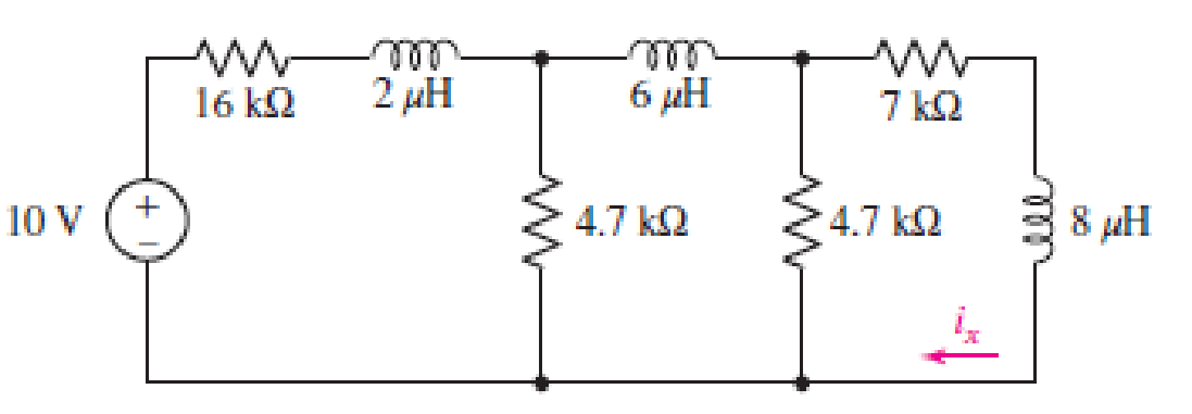
(a)
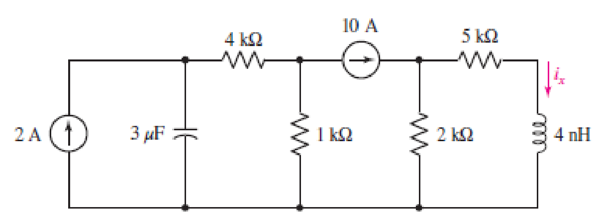
(b)
Expert Solution & Answer
Want to see the full answer?
Check out a sample textbook solution
Students have asked these similar questions
2. Design the voltage regulator circuit of Fig. 7-11 to maintain V, at 12 V across R
with V, that will vary between 16 and 20 V. That is, determine the proper value of Rs
and the power rating of the zener diode (Pz).
R$
V RŽ2402
Fig. 7-11
2. Design the voltage regulator circuit of Fig. 7-11 to maintain VL at 12 V across RL with Vi
that will vary between 16 and 20 V. That is, determine the proper value of Rs and the
power rating of the zener diode (Pz).
Rs
A Vị Rig240N
V;
Fig. (7-11)
Example 7-3:
The reverse current in a certain 12 V, 2.4 W zener diode must be at least 5 mA to ensure that
the diode remains in breakdown. The diode is to be used in the regulator circuit shown in Fig.
7-9, where Vi can vary from 18 V to 24 V. Find a suitable value for RS and the minimum
rated power dissipation that RS should have.
Rs
Solution:
IZK = 5 mA & IZM= Pz/Vz=2.4/12 = 200 mA
V-
Vz
R26002
(when the switch S is open)
= 00
Chapter 7 Solutions
Loose Leaf for Engineering Circuit Analysis Format: Loose-leaf
Ch. 7.1 - Determine the current flowing through a 5 mF...Ch. 7.1 - Prob. 2PCh. 7.1 - Prob. 3PCh. 7.2 - 7.4 The current through a 200 mH inductor is shown...Ch. 7.2 - The current waveform of Fig. 7.14a has equal rise...Ch. 7.2 - Prob. 6PCh. 7.2 - Let L = 25 mH for the inductor of Fig. 7.10. (a)...Ch. 7.3 - Find Ceq for the network of Fig. 7.23. FIGURE...Ch. 7.4 - If vC(t) = 4 cos 105t V in the circuit in Fig....Ch. 7.5 - Derive an expression for vout in terms of vs for...
Ch. 7.6 - Prob. 11PCh. 7 - Making use of the passive sign convention,...Ch. 7 - Prob. 2ECh. 7 - (a) If the voltage waveform depicted in Fig. 7.42...Ch. 7 - A capacitor is constructed from two brass plates,...Ch. 7 - Prob. 5ECh. 7 - Prob. 6ECh. 7 - Design a capacitor whose capacitance can be varied...Ch. 7 - Design a capacitor whose capacitance can be varied...Ch. 7 - Prob. 9ECh. 7 - Assuming the passive sign convention, sketch the...Ch. 7 - Prob. 11ECh. 7 - Prob. 12ECh. 7 - Prob. 13ECh. 7 - Calculate the power dissipated in the 40 resistor...Ch. 7 - Prob. 15ECh. 7 - Design a 30 nH inductor using 28 AWG solid soft...Ch. 7 - Prob. 17ECh. 7 - Prob. 18ECh. 7 - Prob. 19ECh. 7 - Prob. 20ECh. 7 - Calculate vL and iL for each of the circuits...Ch. 7 - The current waveform shown in Fig. 7.14 has a rise...Ch. 7 - Determine the inductor voltage which results from...Ch. 7 - Prob. 24ECh. 7 - The voltage across a 2 H inductor is given by vL =...Ch. 7 - Calculate the energy stored in a 1 nH inductor if...Ch. 7 - Determine the amount of energy stored in a 33 mH...Ch. 7 - Making the assumption that the circuits in Fig....Ch. 7 - Calculate the voltage labeled vx in Fig. 7.52,...Ch. 7 - Prob. 30ECh. 7 - Prob. 31ECh. 7 - Determine an equivalent inductance for the network...Ch. 7 - Using as many 1 nH inductors as you like, design...Ch. 7 - Compute the equivalent capacitance Ceq as labeled...Ch. 7 - Prob. 35ECh. 7 - Prob. 36ECh. 7 - Reduce the circuit depicted in Fig. 7.59 to as few...Ch. 7 - Refer to the network shown in Fig. 7.60 and find...Ch. 7 - Prob. 39ECh. 7 - Prob. 40ECh. 7 - Prob. 41ECh. 7 - Prob. 42ECh. 7 - Prob. 43ECh. 7 - Prob. 44ECh. 7 - Prob. 45ECh. 7 - Prob. 46ECh. 7 - Prob. 47ECh. 7 - Let vs = 100e80t V with no initial energy stored...Ch. 7 - Prob. 49ECh. 7 - Prob. 50ECh. 7 - Interchange the location of R1 and Cf in the...Ch. 7 - For the integrating amplifier circuit of Fig....Ch. 7 - Prob. 53ECh. 7 - For the circuit shown in Fig. 7.73, assume no...Ch. 7 - A new piece of equipment designed to make crystals...Ch. 7 - An altitude sensor on a weather balloon provides a...Ch. 7 - One problem satellites face is exposure to...Ch. 7 - The output of a velocity sensor attached to a...Ch. 7 - A floating sensor in a certain fuel tank is...Ch. 7 - (a) If Is = 3 sin t A, draw the exact dual of the...Ch. 7 - Draw the exact dual of the simple circuit shown in...Ch. 7 - (a) Draw the exact dual of the simple circuit...Ch. 7 - (a) Draw the exact dual of the simple circuit...Ch. 7 - Prob. 64ECh. 7 - Prob. 65ECh. 7 - Prob. 66ECh. 7 - Prob. 67ECh. 7 - Prob. 68ECh. 7 - Prob. 69ECh. 7 - Prob. 70ECh. 7 - For the circuit of Fig. 7.28, (a) sketch vout over...Ch. 7 - (a) Sketch the output function vout of the...Ch. 7 - For the circuit of Fig. 7.72, (a) sketch vout over...
Knowledge Booster


Learn more about
Need a deep-dive on the concept behind this application? Look no further. Learn more about this topic, electrical-engineering and related others by exploring similar questions and additional content below.Similar questions
- 3. The 6-V zener diode in Fig. 7-12 has a maximum rated power dissipated of 690 mW. Its reverse current must be at least 3 mA to keep it in breakdown. Find a suitable value for RS if Vi can vary from 9 V to 12 V and RL can vary from 500 2 to 1.2 k2. Rs Is RL V Fig. (7-12) 4. If Rs in Exercise 3 is set equal to its maximum permissible value, what is the maximum permissible value of V;? 5. If Rs in Exercise 3 is set equal to its minimum permissible value, what is the minimum permissible value of R1? 6. If Rs in Exercise 3 is set equal to 120 2, what is the minimum rated power dissipated that Rs should have?arrow_forwardMaking the assumption that the circuits in Fig. 7.50 have been connected for a very long time, determine the value for each current labeled ix.arrow_forwardQuestion 7.21 Enrichment-type MOSFETFor the voltage divider configuration of Fig. 7.98, determine:a. IDQ and VGSQ.b. VD and VS.arrow_forward
- 3. The 6-V zener diode in Fig. 7-12 has a maximum rated power dissipated of 690 mW. Its reverse current must be at least 3 mA to keep it in breakdown. Find a suitable value for Rs if V, can vary from 9 V to 12 V and R₁ can vary from 500 Ω to 1.2 ΚΩ. R Is RL Fig. 7-12 5. If Rs in Exercise 3 is set equal to its minimum permissible value, what is the minimum permissible value of R₁?arrow_forward3. The 6-V zener diode in Fig. 7-12 has a maximum rated power dissipated of 690 mW. Its reverse current must be at least 3 mA to keep it in breakdown. Find a suitable value for Rs if V, can vary from 9 V to 12 V and R₁ can vary from 500 Ω to 1.2 ΚΩ. V Fig. 7-12arrow_forward3. The 6-V zener diode in Fig. 7-12 has a maximum rated power dissipated of 690 mW. Its reverse current must be at least 3 mA to keep it in breakdown. Find a suitable value for RS if Vi can vary from 9 V to 12 V and R1, can vary from 5002 to 1.2 k2. Rs RL 19 Fig. (7-12)arrow_forward
- 2. For the fixed-bias configuration of Fig. 7.76, determine: a. Ip, and VGS, using a purely mathematical approach. b. Repeat part (a) using a graphical approach and compare results. c. Find VDs, VD, VG, and Vs using the results of part (a). 16 V -3 V 2.2 k2 1.2 M2 = 10 mA Ipss Vp =-4.5 V Vaso FIG. 7.76arrow_forward3. The 6-V zener diode in Fig. 7-12 has a maximum rated power dissipated of 690 mW. Its reverse current must be at least 3 mA to keep it in breakdown. Find a suitable value for Rs if V can vary from 9 V to 12 V and R₁ can vary from 500 Ω to 1.2 ΚΩ. R www V₁ Fig. 7-12 6. If Rs in Exercise 3 is set equal to 120 2, what is the minimum rated power dissipated that Rs should have?arrow_forward2. Design the voltage regulator circuit of Fig. 7-11 to maintain V₁ at 12 V across R₂ with V; that will vary between 16 and 20 V. That is, determine the proper value of Rs and the power rating of the zener diode (Pz). Rs www Vi V₁RL $240A Fig. 7-11arrow_forward
- Question 7.15 Common gate configuration For the network of Fig. 7.92, determine:a. IDQ and VGSQ.b. VDS and VS.arrow_forward3. The 6-V zener diode in Fig. 7-12 has a maximum rated power dissipated of 690 mW. Its reverse current must be at least 3 mA to keep it in breakdown. Find a suitable value for Rs if V, can vary from 9 V to 12 V and R₁ can vary from 500 Ω to 1.2 ΚΩ. R R₁ Fig. 7-12 4. If Rs in Exercise 3 is set equal to its maximum permissible value, what is the maximum permissible value of V?arrow_forwardThe reverse current in a certain 12 V, 2.4 W zener diode must be at least 5 mA to ensure that the diode remains in breakdown. The diode is to be used in the regulator circuit shown in Fig. 7-9, where V, can vary from 18 V to 24 V. Find a suitable value for Rs and the minimum rated power dissipation that Rs should have. R$ R36002arrow_forward
arrow_back_ios
SEE MORE QUESTIONS
arrow_forward_ios
Recommended textbooks for you
 Introductory Circuit Analysis (13th Edition)Electrical EngineeringISBN:9780133923605Author:Robert L. BoylestadPublisher:PEARSON
 Delmar's Standard Textbook Of ElectricityElectrical EngineeringISBN:9781337900348Author:Stephen L. HermanPublisher:Cengage Learning
 Programmable Logic ControllersElectrical EngineeringISBN:9780073373843Author:Frank D. PetruzellaPublisher:McGraw-Hill Education
 Fundamentals of Electric CircuitsElectrical EngineeringISBN:9780078028229Author:Charles K Alexander, Matthew SadikuPublisher:McGraw-Hill Education
 Electric Circuits. (11th Edition)Electrical EngineeringISBN:9780134746968Author:James W. Nilsson, Susan RiedelPublisher:PEARSON
 Engineering ElectromagneticsElectrical EngineeringISBN:9780078028151Author:Hayt, William H. (william Hart), Jr, BUCK, John A.Publisher:Mcgraw-hill Education,
Introductory Circuit Analysis (13th Edition)
Electrical Engineering
ISBN:9780133923605
Author:Robert L. Boylestad
Publisher:PEARSON
Delmar's Standard Textbook Of Electricity
Electrical Engineering
ISBN:9781337900348
Author:Stephen L. Herman
Publisher:Cengage Learning
Programmable Logic Controllers
Electrical Engineering
ISBN:9780073373843
Author:Frank D. Petruzella
Publisher:McGraw-Hill Education
Fundamentals of Electric Circuits
Electrical Engineering
ISBN:9780078028229
Author:Charles K Alexander, Matthew Sadiku
Publisher:McGraw-Hill Education
Electric Circuits. (11th Edition)
Electrical Engineering
ISBN:9780134746968
Author:James W. Nilsson, Susan Riedel
Publisher:PEARSON
Engineering Electromagnetics
Electrical Engineering
ISBN:9780078028151
Author:Hayt, William H. (william Hart), Jr, BUCK, John A.
Publisher:Mcgraw-hill Education,
Current Divider Rule; Author: Neso Academy;https://www.youtube.com/watch?v=hRU1mKWUehY;License: Standard YouTube License, CC-BY