
Loose Leaf for Engineering Circuit Analysis Format: Loose-leaf
9th Edition
ISBN: 9781259989452
Author: Hayt
Publisher: Mcgraw Hill Publishers
expand_more
expand_more
format_list_bulleted
Concept explainers
Videos
Textbook Question
Chapter 7, Problem 14E
Calculate the power dissipated in the 40 Ω resistor and the voltage labeled vC in each of the circuits depicted in Fig. 7.45.
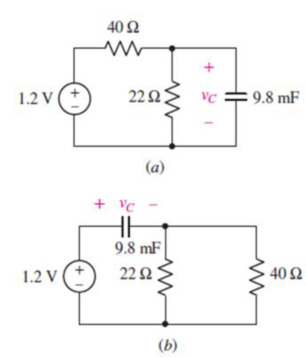
FIGURE 7.45
Expert Solution & Answer
Want to see the full answer?
Check out a sample textbook solution
Students have asked these similar questions
5. Determine Vp and VGs for the fixed-bias configuration of Fig. 7.79.
18 V
2 k2
VD
Ipss = 8 mA
Ve =-4 V
2 ΜΩ
4 V
FIG. 7.79
Problem 5.
Reduce the circuit depicted in Fig. 7.58 to as few components as possible.
2 V
+
R
W
ww
R
R
M
FIGURE 7.58
с
R
+
Vx
CL
ell
R
мее
L
C
PROBLE M 7.15
Determine VOUT versus vIN for the circuit shown in Figure 7.8
Assume that the MOSFET operates in saturation and is characterized by the paramete
K and VT. What is the value of VOUT when VỊN =
0?
PROBLEM 7.16 Determine vo versus vị for the circuit shown in Figure 7.8
Assume that the MOSFET operates in saturation and is characterized by the paramete
K and VT. What is the value of vo when vj =
= 0?
Chapter 7 Solutions
Loose Leaf for Engineering Circuit Analysis Format: Loose-leaf
Ch. 7.1 - Determine the current flowing through a 5 mF...Ch. 7.1 - Prob. 2PCh. 7.1 - Prob. 3PCh. 7.2 - 7.4 The current through a 200 mH inductor is shown...Ch. 7.2 - The current waveform of Fig. 7.14a has equal rise...Ch. 7.2 - Prob. 6PCh. 7.2 - Let L = 25 mH for the inductor of Fig. 7.10. (a)...Ch. 7.3 - Find Ceq for the network of Fig. 7.23. FIGURE...Ch. 7.4 - If vC(t) = 4 cos 105t V in the circuit in Fig....Ch. 7.5 - Derive an expression for vout in terms of vs for...
Ch. 7.6 - Prob. 11PCh. 7 - Making use of the passive sign convention,...Ch. 7 - Prob. 2ECh. 7 - (a) If the voltage waveform depicted in Fig. 7.42...Ch. 7 - A capacitor is constructed from two brass plates,...Ch. 7 - Prob. 5ECh. 7 - Prob. 6ECh. 7 - Design a capacitor whose capacitance can be varied...Ch. 7 - Design a capacitor whose capacitance can be varied...Ch. 7 - Prob. 9ECh. 7 - Assuming the passive sign convention, sketch the...Ch. 7 - Prob. 11ECh. 7 - Prob. 12ECh. 7 - Prob. 13ECh. 7 - Calculate the power dissipated in the 40 resistor...Ch. 7 - Prob. 15ECh. 7 - Design a 30 nH inductor using 28 AWG solid soft...Ch. 7 - Prob. 17ECh. 7 - Prob. 18ECh. 7 - Prob. 19ECh. 7 - Prob. 20ECh. 7 - Calculate vL and iL for each of the circuits...Ch. 7 - The current waveform shown in Fig. 7.14 has a rise...Ch. 7 - Determine the inductor voltage which results from...Ch. 7 - Prob. 24ECh. 7 - The voltage across a 2 H inductor is given by vL =...Ch. 7 - Calculate the energy stored in a 1 nH inductor if...Ch. 7 - Determine the amount of energy stored in a 33 mH...Ch. 7 - Making the assumption that the circuits in Fig....Ch. 7 - Calculate the voltage labeled vx in Fig. 7.52,...Ch. 7 - Prob. 30ECh. 7 - Prob. 31ECh. 7 - Determine an equivalent inductance for the network...Ch. 7 - Using as many 1 nH inductors as you like, design...Ch. 7 - Compute the equivalent capacitance Ceq as labeled...Ch. 7 - Prob. 35ECh. 7 - Prob. 36ECh. 7 - Reduce the circuit depicted in Fig. 7.59 to as few...Ch. 7 - Refer to the network shown in Fig. 7.60 and find...Ch. 7 - Prob. 39ECh. 7 - Prob. 40ECh. 7 - Prob. 41ECh. 7 - Prob. 42ECh. 7 - Prob. 43ECh. 7 - Prob. 44ECh. 7 - Prob. 45ECh. 7 - Prob. 46ECh. 7 - Prob. 47ECh. 7 - Let vs = 100e80t V with no initial energy stored...Ch. 7 - Prob. 49ECh. 7 - Prob. 50ECh. 7 - Interchange the location of R1 and Cf in the...Ch. 7 - For the integrating amplifier circuit of Fig....Ch. 7 - Prob. 53ECh. 7 - For the circuit shown in Fig. 7.73, assume no...Ch. 7 - A new piece of equipment designed to make crystals...Ch. 7 - An altitude sensor on a weather balloon provides a...Ch. 7 - One problem satellites face is exposure to...Ch. 7 - The output of a velocity sensor attached to a...Ch. 7 - A floating sensor in a certain fuel tank is...Ch. 7 - (a) If Is = 3 sin t A, draw the exact dual of the...Ch. 7 - Draw the exact dual of the simple circuit shown in...Ch. 7 - (a) Draw the exact dual of the simple circuit...Ch. 7 - (a) Draw the exact dual of the simple circuit...Ch. 7 - Prob. 64ECh. 7 - Prob. 65ECh. 7 - Prob. 66ECh. 7 - Prob. 67ECh. 7 - Prob. 68ECh. 7 - Prob. 69ECh. 7 - Prob. 70ECh. 7 - For the circuit of Fig. 7.28, (a) sketch vout over...Ch. 7 - (a) Sketch the output function vout of the...Ch. 7 - For the circuit of Fig. 7.72, (a) sketch vout over...
Knowledge Booster


Learn more about
Need a deep-dive on the concept behind this application? Look no further. Learn more about this topic, electrical-engineering and related others by exploring similar questions and additional content below.Similar questions
- . Calculate v, and i̟ for each of the circuits depicted in Fig. 7.48, if i, = 1 mA and v, = 2.1 V. iL 14 kN is 12 nH 4.7 kN llarrow_forwardQuestion 14 Calculate the power dissipated in the 40 22 resistor and the voltage labeled vc in each of the circuits depicted in Fig. 7.44. 40 Ω 1.2 V 22 02 (a) + "C 9.8 mF 1.2 V + VC 9.8 mF 22 Ω (b) ww 40 Ωarrow_forwardCalculate vL and ir for each of the circuits depicted in Fig. 7.48, if i, = 1 mA and v, = 2 V. 4.7 kΩ 14 kΩ 12 nH 12 nH 4.7 kN elearrow_forward
- Q2 o 20 V For the network of Fig. 7.85, determine: 2.2 kn a. VG- b. Ipo and VGSo c. Vp and Vs- d. Vpsg 910 k2 DO Dss = 10 mA Vp =-3.5 V VG +] Vaso 110 kΩ 1.1 k2arrow_forward2. For the fixed-bias configuration of Fig. 7.76, determine: a. Ipo and VGS using a purely mathematical approach. b. Repeat part (a) using a graphical approach and compare results. c. Find Vps, VD, VG, and Vs using the results of part (a). -3 V * 1.2 ΜΩ VGSQ 16 V 1 2.2 ΚΩ PROBLEMS Fixed-Bias Configuration 100 pss = 10 mA Vp = -4.5V 3. Given the measured value of V₁ in Fig. 7.77, determine: a. Ip. b. Vps. c. VGG VD=6V 12 V 2.2 kΩ ID VGS 10 = 1 (1 - Vec)² ID Vp + VDS Inss=8 mA Vp=-4 V FIG. 7.77 Problem 3. 1 ΜΩ -VGG 50arrow_forwardDetermine the value of Rs for the network of Fig. 7.87 to establish Vp = 10 V. 20 V 2 ΚΩ R₁ →o Vp = 10 V Ipss = 12 mA Vp=-8V 36 ΚΩ 12 ΚΩ Rp. + Rsarrow_forward
- Determine vo for the circuit shown in Figure 7.98(a) and (b). 12 V Si 22 ka Si 1.8 k2 10 k2 -12 V (a) (b) Figure 7.8arrow_forward× 7:53 www.bartleby.com Homework Help is Here - Start Your Trial Now! Q SEARCH Textbook Question 个 R₁ = 7,2 kn Fig. 7.69 Chapter 7, Problem 6P The total resistance R+ for the network of Fig. 7.69. is 7.2 k Find the resistance R. R₁ vport Solution ASK R₁ il 5GE ncwa R₁ R₁ G ●●● → 2arrow_forwardA dc constant voltage source feeds a resistance of 2,000 kΩ in series with a 5µF capacitor. Find the time taken for the capacitor when the charge retained will be decayed to 50% of the initial value, the voltage sourcing being short circuited. Ans 11arrow_forward
- Give reason : a) The total resistance in a circuit with parallel resistors increases , if one of the parallel resistors opens . b) If the inductor is charged it acts as an open circuit. c) If the capacitor is fully discharged it acts as a short circuit .arrow_forward2. Determine RT for the networks of Fig. 7.65. 4Ω R RT 4Ω (a) (b) 4Ω 4Ω 4Ω 4Ω RT RT (c) (d) FIG. 7.65 Problem 2.arrow_forward3. The 6-V zener diode in Fig. 7-12 has a maximum rated power dissipated of 690 mW. Its reverse current must be at least 3 mA to keep it in breakdown. Find a suitable value for Rs if V; can vary from 9 V to 12 V and R₁ can vary from 500 Ω to 1.2 kΩ. R I RL Fig. 7-12 6Varrow_forward
arrow_back_ios
SEE MORE QUESTIONS
arrow_forward_ios
Recommended textbooks for you
 Introductory Circuit Analysis (13th Edition)Electrical EngineeringISBN:9780133923605Author:Robert L. BoylestadPublisher:PEARSON
 Delmar's Standard Textbook Of ElectricityElectrical EngineeringISBN:9781337900348Author:Stephen L. HermanPublisher:Cengage Learning
 Programmable Logic ControllersElectrical EngineeringISBN:9780073373843Author:Frank D. PetruzellaPublisher:McGraw-Hill Education
 Fundamentals of Electric CircuitsElectrical EngineeringISBN:9780078028229Author:Charles K Alexander, Matthew SadikuPublisher:McGraw-Hill Education
 Electric Circuits. (11th Edition)Electrical EngineeringISBN:9780134746968Author:James W. Nilsson, Susan RiedelPublisher:PEARSON
 Engineering ElectromagneticsElectrical EngineeringISBN:9780078028151Author:Hayt, William H. (william Hart), Jr, BUCK, John A.Publisher:Mcgraw-hill Education,
Introductory Circuit Analysis (13th Edition)
Electrical Engineering
ISBN:9780133923605
Author:Robert L. Boylestad
Publisher:PEARSON
Delmar's Standard Textbook Of Electricity
Electrical Engineering
ISBN:9781337900348
Author:Stephen L. Herman
Publisher:Cengage Learning
Programmable Logic Controllers
Electrical Engineering
ISBN:9780073373843
Author:Frank D. Petruzella
Publisher:McGraw-Hill Education
Fundamentals of Electric Circuits
Electrical Engineering
ISBN:9780078028229
Author:Charles K Alexander, Matthew Sadiku
Publisher:McGraw-Hill Education
Electric Circuits. (11th Edition)
Electrical Engineering
ISBN:9780134746968
Author:James W. Nilsson, Susan Riedel
Publisher:PEARSON
Engineering Electromagnetics
Electrical Engineering
ISBN:9780078028151
Author:Hayt, William H. (william Hart), Jr, BUCK, John A.
Publisher:Mcgraw-hill Education,
Current Divider Rule; Author: Neso Academy;https://www.youtube.com/watch?v=hRU1mKWUehY;License: Standard YouTube License, CC-BY