
Loose Leaf for Engineering Circuit Analysis Format: Loose-leaf
9th Edition
ISBN: 9781259989452
Author: Hayt
Publisher: Mcgraw Hill Publishers
expand_more
expand_more
format_list_bulleted
Concept explainers
Videos
Textbook Question
Chapter 7, Problem 3E
(a) If the voltage waveform depicted in Fig. 7.42 is applied across the terminals of a 1 μF electrolytic capacitor, graph the resulting current for t > 0, assuming the passive sign convention. (b) Repeat part (a) if the capacitor is replaced with a 20 nF capacitor.
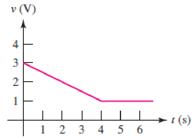
■ FIGURE 7.42
Expert Solution & Answer
Want to see the full answer?
Check out a sample textbook solution
Students have asked these similar questions
A capacitor is rated at 1000uF of capacitance. Ifits minimum value is 850uF, what is its maximumallowable value assuming it has a 15% tolerance?
Consider the capacitor and its voltages for these two questions.
a. What is the current i at 3s (in A)?
b. What is the current i at 7s (in mA)?
Please also answer the last question for checking.
#14 The "charge-holding" ability of a capacitor is called its capacitance.
a
True
b
False
Chapter 7 Solutions
Loose Leaf for Engineering Circuit Analysis Format: Loose-leaf
Ch. 7.1 - Determine the current flowing through a 5 mF...Ch. 7.1 - Prob. 2PCh. 7.1 - Prob. 3PCh. 7.2 - 7.4 The current through a 200 mH inductor is shown...Ch. 7.2 - The current waveform of Fig. 7.14a has equal rise...Ch. 7.2 - Prob. 6PCh. 7.2 - Let L = 25 mH for the inductor of Fig. 7.10. (a)...Ch. 7.3 - Find Ceq for the network of Fig. 7.23. FIGURE...Ch. 7.4 - If vC(t) = 4 cos 105t V in the circuit in Fig....Ch. 7.5 - Derive an expression for vout in terms of vs for...
Ch. 7.6 - Prob. 11PCh. 7 - Making use of the passive sign convention,...Ch. 7 - Prob. 2ECh. 7 - (a) If the voltage waveform depicted in Fig. 7.42...Ch. 7 - A capacitor is constructed from two brass plates,...Ch. 7 - Prob. 5ECh. 7 - Prob. 6ECh. 7 - Design a capacitor whose capacitance can be varied...Ch. 7 - Design a capacitor whose capacitance can be varied...Ch. 7 - Prob. 9ECh. 7 - Assuming the passive sign convention, sketch the...Ch. 7 - Prob. 11ECh. 7 - Prob. 12ECh. 7 - Prob. 13ECh. 7 - Calculate the power dissipated in the 40 resistor...Ch. 7 - Prob. 15ECh. 7 - Design a 30 nH inductor using 28 AWG solid soft...Ch. 7 - Prob. 17ECh. 7 - Prob. 18ECh. 7 - Prob. 19ECh. 7 - Prob. 20ECh. 7 - Calculate vL and iL for each of the circuits...Ch. 7 - The current waveform shown in Fig. 7.14 has a rise...Ch. 7 - Determine the inductor voltage which results from...Ch. 7 - Prob. 24ECh. 7 - The voltage across a 2 H inductor is given by vL =...Ch. 7 - Calculate the energy stored in a 1 nH inductor if...Ch. 7 - Determine the amount of energy stored in a 33 mH...Ch. 7 - Making the assumption that the circuits in Fig....Ch. 7 - Calculate the voltage labeled vx in Fig. 7.52,...Ch. 7 - Prob. 30ECh. 7 - Prob. 31ECh. 7 - Determine an equivalent inductance for the network...Ch. 7 - Using as many 1 nH inductors as you like, design...Ch. 7 - Compute the equivalent capacitance Ceq as labeled...Ch. 7 - Prob. 35ECh. 7 - Prob. 36ECh. 7 - Reduce the circuit depicted in Fig. 7.59 to as few...Ch. 7 - Refer to the network shown in Fig. 7.60 and find...Ch. 7 - Prob. 39ECh. 7 - Prob. 40ECh. 7 - Prob. 41ECh. 7 - Prob. 42ECh. 7 - Prob. 43ECh. 7 - Prob. 44ECh. 7 - Prob. 45ECh. 7 - Prob. 46ECh. 7 - Prob. 47ECh. 7 - Let vs = 100e80t V with no initial energy stored...Ch. 7 - Prob. 49ECh. 7 - Prob. 50ECh. 7 - Interchange the location of R1 and Cf in the...Ch. 7 - For the integrating amplifier circuit of Fig....Ch. 7 - Prob. 53ECh. 7 - For the circuit shown in Fig. 7.73, assume no...Ch. 7 - A new piece of equipment designed to make crystals...Ch. 7 - An altitude sensor on a weather balloon provides a...Ch. 7 - One problem satellites face is exposure to...Ch. 7 - The output of a velocity sensor attached to a...Ch. 7 - A floating sensor in a certain fuel tank is...Ch. 7 - (a) If Is = 3 sin t A, draw the exact dual of the...Ch. 7 - Draw the exact dual of the simple circuit shown in...Ch. 7 - (a) Draw the exact dual of the simple circuit...Ch. 7 - (a) Draw the exact dual of the simple circuit...Ch. 7 - Prob. 64ECh. 7 - Prob. 65ECh. 7 - Prob. 66ECh. 7 - Prob. 67ECh. 7 - Prob. 68ECh. 7 - Prob. 69ECh. 7 - Prob. 70ECh. 7 - For the circuit of Fig. 7.28, (a) sketch vout over...Ch. 7 - (a) Sketch the output function vout of the...Ch. 7 - For the circuit of Fig. 7.72, (a) sketch vout over...
Knowledge Booster


Learn more about
Need a deep-dive on the concept behind this application? Look no further. Learn more about this topic, electrical-engineering and related others by exploring similar questions and additional content below.Similar questions
- A capacitor sensor consists of 3 charged parallel plates have breath of 500 mm. These plates are separated from each other by 7.5 mm. When, the middle plate is moving up by 0.25 mm. Assuming upper and lower plates kept fixed, calculate the following, i. Length of the capacitor plates, if the total change in capacitance is 1.190 pF ii. Values of C1 and C2.arrow_forwardDetermine (a) the equivalent capacitance ,(b) the total charge and (c) the total stored energy of the electronic capacitor circuit.arrow_forward(b) A medical technology company is designing a new portable defibrillator for reviving patients whose heart has stopped. The capacitor in the device will be charged to 2000 V and is required to deliver 400 J of energy on discharge. i) Calculate the capacitance required for this capacitor ii) The conducting plates of the capacitor must have an area of 5 m² and be separated by an insulator with thickness of 0.05 mm. Determine the value of dielectric constant for the insulator between the capacitor parallel plates to deliver the intended energy to the patientarrow_forward
- Q1 (True/False): A) The current through the capacitor is inversely proportional to the derivative of the voltage across it: Is it true or false? B) In a typical electronic circuit the capacitor blocks DC and couplest he AC to the next stage of the circuit: Is it true or false? C) The more the value of the stray capacitance , the better it is: Is it true or false?arrow_forwardExample 7.33. Two coils of inductances 4 and 6 henry are connected in parallel. If their mutual inductance is 3 henry, calculate the equivalent inductance of the combination if (i) mutual inductance assists the self-inductance (ii) mutual inductance opposes the self-inductance.arrow_forward1. A capacitor is rated at 1000uF of capacitance. If its minimum value is 850uF, what is its maximum allowable value assuming it has a 15% tolerance?arrow_forward
- A 2.5-µH inductor has a resistance of 23 V. At a frequency of 35 MHz, find its Q. (round-off your answer to whole number with correct unit) *arrow_forwardA capacitor of 8µF capacitance is connected to a d.c.source through a resistance of 1 megaohm.Calculate the time taken by the capacitor to receive 95% of its final charge.How long will it take the capacitor to be jully charged?arrow_forwardFind the current i(t) for the capacitor. (Complete solution and explanation)arrow_forward
- The current flowing through a 0.800 mF capacitor is shown in the figure below, Assume the passive sign convention. 1(A) 8 0 0.2 0.4 0.6 0.8 1.0 1.2 1.4 →1(5) The capacitance of the capacitor is 0,800mF. (Round the final answer to three decimal places.) Compute the voltage at 200ms. 600ms and 1.2s. The voltage at 200 ms is [V.600ms is ] Vand 1.2s isarrow_forward7.49.2 For the RC circuit shown in the image below, the current waveform is applied. If v (0) = 0, R1 = 4 S2 and R2 = 9 $2, determine the voltage across the capacitor, v when t = 1.1 s. Please pay attention: the numbers may change since they are randomized. Your answer must include 3 places after the decimal point, and the proper SI unit. is (A) A 1 t (s) (a) R2 + is R, 0.5 F (b) Your Answer: Answer unitsarrow_forward4 Calculate the equivalent capacitance, voltage, and accumulated charge oneach capacitorarrow_forward
arrow_back_ios
SEE MORE QUESTIONS
arrow_forward_ios
Recommended textbooks for you
 Introductory Circuit Analysis (13th Edition)Electrical EngineeringISBN:9780133923605Author:Robert L. BoylestadPublisher:PEARSON
 Delmar's Standard Textbook Of ElectricityElectrical EngineeringISBN:9781337900348Author:Stephen L. HermanPublisher:Cengage Learning
 Programmable Logic ControllersElectrical EngineeringISBN:9780073373843Author:Frank D. PetruzellaPublisher:McGraw-Hill Education
 Fundamentals of Electric CircuitsElectrical EngineeringISBN:9780078028229Author:Charles K Alexander, Matthew SadikuPublisher:McGraw-Hill Education
 Electric Circuits. (11th Edition)Electrical EngineeringISBN:9780134746968Author:James W. Nilsson, Susan RiedelPublisher:PEARSON
 Engineering ElectromagneticsElectrical EngineeringISBN:9780078028151Author:Hayt, William H. (william Hart), Jr, BUCK, John A.Publisher:Mcgraw-hill Education,
Introductory Circuit Analysis (13th Edition)
Electrical Engineering
ISBN:9780133923605
Author:Robert L. Boylestad
Publisher:PEARSON
Delmar's Standard Textbook Of Electricity
Electrical Engineering
ISBN:9781337900348
Author:Stephen L. Herman
Publisher:Cengage Learning
Programmable Logic Controllers
Electrical Engineering
ISBN:9780073373843
Author:Frank D. Petruzella
Publisher:McGraw-Hill Education
Fundamentals of Electric Circuits
Electrical Engineering
ISBN:9780078028229
Author:Charles K Alexander, Matthew Sadiku
Publisher:McGraw-Hill Education
Electric Circuits. (11th Edition)
Electrical Engineering
ISBN:9780134746968
Author:James W. Nilsson, Susan Riedel
Publisher:PEARSON
Engineering Electromagnetics
Electrical Engineering
ISBN:9780078028151
Author:Hayt, William H. (william Hart), Jr, BUCK, John A.
Publisher:Mcgraw-hill Education,
Capacitors Explained - The basics how capacitors work working principle; Author: The Engineering Mindset;https://www.youtube.com/watch?v=X4EUwTwZ110;License: Standard YouTube License, CC-BY