
Loose Leaf for Engineering Circuit Analysis Format: Loose-leaf
9th Edition
ISBN: 9781259989452
Author: Hayt
Publisher: Mcgraw Hill Publishers
expand_more
expand_more
format_list_bulleted
Concept explainers
Videos
Textbook Question
Chapter 7, Problem 71E
For the circuit of Fig. 7.28, (a) sketch vout over the range of 0 ≤ t ≤ 5 ms if Rf = 1 kΩ, C1 = 1 nF, and vs is a 1 kHz sinusoidal source having a peak voltage of 2 V. (b) Using ±15 V supplies for the op amp, perform an appropriate transient simulation and plot vout.
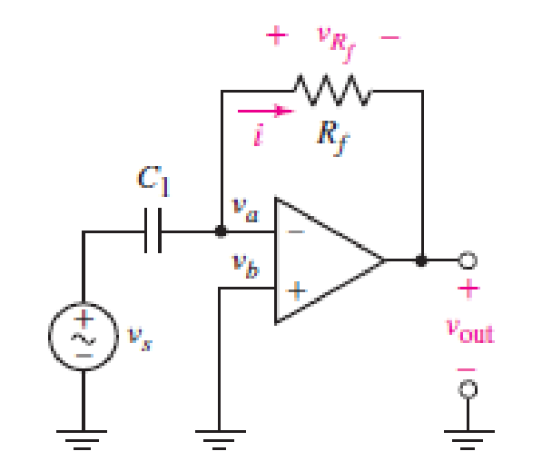
■ FIGURE 7.28 An ideal op amp connected as a differentiator.
Expert Solution & Answer
Want to see the full answer?
Check out a sample textbook solution
Students have asked these similar questions
OP-AMP Review questions
(7.2) If the values of the resistors are given as: R1= 27KN, R2= 82KN, R3= 10K2, R4= 12KN, R5=
39KN, R6= 56 KN, Find the expression for the output voltage in terms of Vx, Vy, Vz. For better
accuracy of the answers, use 4 decimal places.
R,
R
R6
A time-varying signal E; is applied to the (-) input terminal and ground to the (+) input terminal of an op-amp LM741.
Sketch accurately:
(a) Vo vs t
(b) Vo vs E
Circle the right answer:
The circuit is:
(a) An inverting zero-crossing detector
(b) A non- inverting zero-crossing detector
E, vs. I
+15 V
+3
E,
LM741
t (ms)
8
10 k2
-3
-15 V
electric circuit analysis
electric circuit fundamentals by franco
chapter 7 problem 7.35
Chapter 7 Solutions
Loose Leaf for Engineering Circuit Analysis Format: Loose-leaf
Ch. 7.1 - Determine the current flowing through a 5 mF...Ch. 7.1 - Prob. 2PCh. 7.1 - Prob. 3PCh. 7.2 - 7.4 The current through a 200 mH inductor is shown...Ch. 7.2 - The current waveform of Fig. 7.14a has equal rise...Ch. 7.2 - Prob. 6PCh. 7.2 - Let L = 25 mH for the inductor of Fig. 7.10. (a)...Ch. 7.3 - Find Ceq for the network of Fig. 7.23. FIGURE...Ch. 7.4 - If vC(t) = 4 cos 105t V in the circuit in Fig....Ch. 7.5 - Derive an expression for vout in terms of vs for...
Ch. 7.6 - Prob. 11PCh. 7 - Making use of the passive sign convention,...Ch. 7 - Prob. 2ECh. 7 - (a) If the voltage waveform depicted in Fig. 7.42...Ch. 7 - A capacitor is constructed from two brass plates,...Ch. 7 - Prob. 5ECh. 7 - Prob. 6ECh. 7 - Design a capacitor whose capacitance can be varied...Ch. 7 - Design a capacitor whose capacitance can be varied...Ch. 7 - Prob. 9ECh. 7 - Assuming the passive sign convention, sketch the...Ch. 7 - Prob. 11ECh. 7 - Prob. 12ECh. 7 - Prob. 13ECh. 7 - Calculate the power dissipated in the 40 resistor...Ch. 7 - Prob. 15ECh. 7 - Design a 30 nH inductor using 28 AWG solid soft...Ch. 7 - Prob. 17ECh. 7 - Prob. 18ECh. 7 - Prob. 19ECh. 7 - Prob. 20ECh. 7 - Calculate vL and iL for each of the circuits...Ch. 7 - The current waveform shown in Fig. 7.14 has a rise...Ch. 7 - Determine the inductor voltage which results from...Ch. 7 - Prob. 24ECh. 7 - The voltage across a 2 H inductor is given by vL =...Ch. 7 - Calculate the energy stored in a 1 nH inductor if...Ch. 7 - Determine the amount of energy stored in a 33 mH...Ch. 7 - Making the assumption that the circuits in Fig....Ch. 7 - Calculate the voltage labeled vx in Fig. 7.52,...Ch. 7 - Prob. 30ECh. 7 - Prob. 31ECh. 7 - Determine an equivalent inductance for the network...Ch. 7 - Using as many 1 nH inductors as you like, design...Ch. 7 - Compute the equivalent capacitance Ceq as labeled...Ch. 7 - Prob. 35ECh. 7 - Prob. 36ECh. 7 - Reduce the circuit depicted in Fig. 7.59 to as few...Ch. 7 - Refer to the network shown in Fig. 7.60 and find...Ch. 7 - Prob. 39ECh. 7 - Prob. 40ECh. 7 - Prob. 41ECh. 7 - Prob. 42ECh. 7 - Prob. 43ECh. 7 - Prob. 44ECh. 7 - Prob. 45ECh. 7 - Prob. 46ECh. 7 - Prob. 47ECh. 7 - Let vs = 100e80t V with no initial energy stored...Ch. 7 - Prob. 49ECh. 7 - Prob. 50ECh. 7 - Interchange the location of R1 and Cf in the...Ch. 7 - For the integrating amplifier circuit of Fig....Ch. 7 - Prob. 53ECh. 7 - For the circuit shown in Fig. 7.73, assume no...Ch. 7 - A new piece of equipment designed to make crystals...Ch. 7 - An altitude sensor on a weather balloon provides a...Ch. 7 - One problem satellites face is exposure to...Ch. 7 - The output of a velocity sensor attached to a...Ch. 7 - A floating sensor in a certain fuel tank is...Ch. 7 - (a) If Is = 3 sin t A, draw the exact dual of the...Ch. 7 - Draw the exact dual of the simple circuit shown in...Ch. 7 - (a) Draw the exact dual of the simple circuit...Ch. 7 - (a) Draw the exact dual of the simple circuit...Ch. 7 - Prob. 64ECh. 7 - Prob. 65ECh. 7 - Prob. 66ECh. 7 - Prob. 67ECh. 7 - Prob. 68ECh. 7 - Prob. 69ECh. 7 - Prob. 70ECh. 7 - For the circuit of Fig. 7.28, (a) sketch vout over...Ch. 7 - (a) Sketch the output function vout of the...Ch. 7 - For the circuit of Fig. 7.72, (a) sketch vout over...
Knowledge Booster


Learn more about
Need a deep-dive on the concept behind this application? Look no further. Learn more about this topic, electrical-engineering and related others by exploring similar questions and additional content below.Similar questions
- OP-AMP Review questions (7.4) Assuming the circuit is a Ideal Op-Amp, derive the voltage gain of the circuit given. Find the input voltage when the output is 10V. Vin 2 KO Vo R1 R2 10 KQ R3 S10 KOarrow_forwardI. Design a suitable op amp circuit to implement the following equation: dv. f = 6(2V, – 4V2) – 3 V, + 2- dt II. An op amp has a GBP of 10°. A 0.8 uV sinusoidal signal at 10 KHz is required to be amplified to 5 V. Calculate the gains and draw the schematic circuit to achieve this.arrow_forwardQ.2 Design an op-amp circuit to produce the output V,= 8Vi, using both inverting and non- inverting circuits.arrow_forward
- a- Compute the voltage gain G, and then the output voltage Vout for the non-inverting 1mV (DC). Plot V and V op amp circuit shown in Figure 7, given that Vin as out versus time on the same set of axes. b- Compute the voltage gain G, and then the output voltage V, op amp circuit shown in Figure 7, given that Vin = sin(t) mV. Plot Vn and V, for the non-inverting out as out versus time on the same set of axes. Rf 120 KN Rin 20 KQ V. out t, Vin R Figure 7: Circuit of example 3arrow_forwardI need the DC analysis for this circuit, hence IC, IE, IB, VB, VC and VE Assume Beta to be 200, capacitors are open circuits in DC analysis and please make a clear explanation of the mode of operationarrow_forward1. Design a suitable op amp circuit to implement the following equation: f = 2(V, - 5v,) + 6 v IL. Derive the characteristic equation of an accelerometer then show how can be used as a seismometer.arrow_forward
- a) Design a non-inverting amplifier using an ideal op amp that has a gain 7.5.b) If you wish to amplify signals between -2V and 1.2V using the circuit you designed in part (a) what arethe smallest power supply voltages you can use?c) Draw your final circuit diagram.d) Assume that the voltage signal source is vs = −1V and the feedback resistor Rf is replaced with avariable resistor. Specify the range of Rf (in kΩ ) which will cause the op amp to saturate?arrow_forwardShow that the ideal op ampin shown will saturate when Ra=R(±VCC-2vg)3vg.arrow_forwardThe input to the circuit below is a symmetric square wave that goes between +£1 V and has a period 1 ms. Make an accurate graph of the output voltage; be sure to label the axes. The op-amp is ideal, and the capacitor on the output is large. The output capacitor blocks any d.c. component. 0.1 uF 10 k vin o voutarrow_forward
- 2) The op amp in the circuit that shown in next figure is ideal and ±15 V is used as power supplies for the op amp IC. Assume that the initial voltage on capacitor is zero and the op amps operates in linear region. If v,=2sin(@t) and R=1 KQ, find the minimum value of the used capacitor. 2R R Rarrow_forwardAt the instant the switch isclosed, the voltage on the capacitor is 56 V. Assume an ideal op amp.How many milliseconds after the switch is closed will the output voltagevo equal zero?arrow_forwardThe op amp in the circuit shown is ideal. Suppose va=2 V. What value of Rf will cause the op amp to saturate?arrow_forward
arrow_back_ios
SEE MORE QUESTIONS
arrow_forward_ios
Recommended textbooks for you
 Introductory Circuit Analysis (13th Edition)Electrical EngineeringISBN:9780133923605Author:Robert L. BoylestadPublisher:PEARSON
 Delmar's Standard Textbook Of ElectricityElectrical EngineeringISBN:9781337900348Author:Stephen L. HermanPublisher:Cengage Learning
 Programmable Logic ControllersElectrical EngineeringISBN:9780073373843Author:Frank D. PetruzellaPublisher:McGraw-Hill Education
 Fundamentals of Electric CircuitsElectrical EngineeringISBN:9780078028229Author:Charles K Alexander, Matthew SadikuPublisher:McGraw-Hill Education
 Electric Circuits. (11th Edition)Electrical EngineeringISBN:9780134746968Author:James W. Nilsson, Susan RiedelPublisher:PEARSON
 Engineering ElectromagneticsElectrical EngineeringISBN:9780078028151Author:Hayt, William H. (william Hart), Jr, BUCK, John A.Publisher:Mcgraw-hill Education,
Introductory Circuit Analysis (13th Edition)
Electrical Engineering
ISBN:9780133923605
Author:Robert L. Boylestad
Publisher:PEARSON
Delmar's Standard Textbook Of Electricity
Electrical Engineering
ISBN:9781337900348
Author:Stephen L. Herman
Publisher:Cengage Learning
Programmable Logic Controllers
Electrical Engineering
ISBN:9780073373843
Author:Frank D. Petruzella
Publisher:McGraw-Hill Education
Fundamentals of Electric Circuits
Electrical Engineering
ISBN:9780078028229
Author:Charles K Alexander, Matthew Sadiku
Publisher:McGraw-Hill Education
Electric Circuits. (11th Edition)
Electrical Engineering
ISBN:9780134746968
Author:James W. Nilsson, Susan Riedel
Publisher:PEARSON
Engineering Electromagnetics
Electrical Engineering
ISBN:9780078028151
Author:Hayt, William H. (william Hart), Jr, BUCK, John A.
Publisher:Mcgraw-hill Education,
ENA 9.2(1)(En)(Alex) Sinusoids & Phasors - Explanation with Example 9.1 ,9.2 & PP 9.2; Author: Electrical Engineering Academy;https://www.youtube.com/watch?v=vX_LLNl-ZpU;License: Standard YouTube License, CC-BY
Electrical Engineering: Ch 10 Alternating Voltages & Phasors (8 of 82) What is a Phasor?; Author: Michel van Biezen;https://www.youtube.com/watch?v=2I1tF3ixNg0;License: Standard Youtube License