
Loose Leaf for Engineering Circuit Analysis Format: Loose-leaf
9th Edition
ISBN: 9781259989452
Author: Hayt
Publisher: Mcgraw Hill Publishers
expand_more
expand_more
format_list_bulleted
Concept explainers
Videos
Textbook Question
Chapter 7, Problem 61E
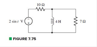 Draw the exact dual of the simple circuit shown in Fig. 7.75. (b) Label the new (dual) variables. (c) Write mesh equations for both circuits.
Expert Solution & Answer
Want to see the full answer?
Check out a sample textbook solution
Students have asked these similar questions
Electrical Engineering
Q7: Using the linear separability concept, obtain the response for OR
function (rake bipolar inputs and bipolar targets).
Table 7
163-164 / 489
Using Thevenin's Theorem, rewrite the physical network from Figure 7 as
an equivalent Thevenin Network, i.e. express Veq as a function of V₁ and V₁ and
Req as a value. If the voltage sources Vo and V₁ are the outputs of digital pins
on an Arduino (i.e. 0 volts or 5 volts), what are the four possible values of Veq?
+
Vol
+
2R
Physical circuit
2R
VO
m
3.3ΚΩ
m
t
Figure 7: Resistor Network for Thevinin's Theorem
Using Thevenin's Theorem rewrite Vout from Figure 8 as a function of vo
through v3. We will consider these voltages to be the inputs of this circuit.
Since they are inputs, they can also be thought of as implicitly declared volt-
age sources. You may expand vo through v3 as voltage sources (referenced to
ground) to make the circuit more clear. For analysis, you will find it most useful
to break the circuit and cascade Thevenin's Theorem from the left most point to
the right most point. Note the pattern that appears with each additional R-2R
m
R
Vout
section in your prelab. If the…
1. For the network in Fig. 7.70:
a. Does Is = I5 = I6? Explain.
b. If Is = 10 A and I1 = 4 A, find I2.
c. Does I1 + I2 = I3 + I4? Explain.
d. If V2 = 8 V and E = 14 V, find V3.
e. If R1 = 4 Ω, R2 = 2 Ω, R3 = 4 Ω, and R4 = 6 Ω, what is RT?
f. If all the resistors of the configuration are 20 Ω, what is the source current if the applied voltage is 20 V?
g. Using the values of part (f), find the power delivered by the battery and the power absorbed by the total resistance RT.
Chapter 7 Solutions
Loose Leaf for Engineering Circuit Analysis Format: Loose-leaf
Ch. 7.1 - Determine the current flowing through a 5 mF...Ch. 7.1 - Prob. 2PCh. 7.1 - Prob. 3PCh. 7.2 - 7.4 The current through a 200 mH inductor is shown...Ch. 7.2 - The current waveform of Fig. 7.14a has equal rise...Ch. 7.2 - Prob. 6PCh. 7.2 - Let L = 25 mH for the inductor of Fig. 7.10. (a)...Ch. 7.3 - Find Ceq for the network of Fig. 7.23. FIGURE...Ch. 7.4 - If vC(t) = 4 cos 105t V in the circuit in Fig....Ch. 7.5 - Derive an expression for vout in terms of vs for...
Ch. 7.6 - Prob. 11PCh. 7 - Making use of the passive sign convention,...Ch. 7 - Prob. 2ECh. 7 - (a) If the voltage waveform depicted in Fig. 7.42...Ch. 7 - A capacitor is constructed from two brass plates,...Ch. 7 - Prob. 5ECh. 7 - Prob. 6ECh. 7 - Design a capacitor whose capacitance can be varied...Ch. 7 - Design a capacitor whose capacitance can be varied...Ch. 7 - Prob. 9ECh. 7 - Assuming the passive sign convention, sketch the...Ch. 7 - Prob. 11ECh. 7 - Prob. 12ECh. 7 - Prob. 13ECh. 7 - Calculate the power dissipated in the 40 resistor...Ch. 7 - Prob. 15ECh. 7 - Design a 30 nH inductor using 28 AWG solid soft...Ch. 7 - Prob. 17ECh. 7 - Prob. 18ECh. 7 - Prob. 19ECh. 7 - Prob. 20ECh. 7 - Calculate vL and iL for each of the circuits...Ch. 7 - The current waveform shown in Fig. 7.14 has a rise...Ch. 7 - Determine the inductor voltage which results from...Ch. 7 - Prob. 24ECh. 7 - The voltage across a 2 H inductor is given by vL =...Ch. 7 - Calculate the energy stored in a 1 nH inductor if...Ch. 7 - Determine the amount of energy stored in a 33 mH...Ch. 7 - Making the assumption that the circuits in Fig....Ch. 7 - Calculate the voltage labeled vx in Fig. 7.52,...Ch. 7 - Prob. 30ECh. 7 - Prob. 31ECh. 7 - Determine an equivalent inductance for the network...Ch. 7 - Using as many 1 nH inductors as you like, design...Ch. 7 - Compute the equivalent capacitance Ceq as labeled...Ch. 7 - Prob. 35ECh. 7 - Prob. 36ECh. 7 - Reduce the circuit depicted in Fig. 7.59 to as few...Ch. 7 - Refer to the network shown in Fig. 7.60 and find...Ch. 7 - Prob. 39ECh. 7 - Prob. 40ECh. 7 - Prob. 41ECh. 7 - Prob. 42ECh. 7 - Prob. 43ECh. 7 - Prob. 44ECh. 7 - Prob. 45ECh. 7 - Prob. 46ECh. 7 - Prob. 47ECh. 7 - Let vs = 100e80t V with no initial energy stored...Ch. 7 - Prob. 49ECh. 7 - Prob. 50ECh. 7 - Interchange the location of R1 and Cf in the...Ch. 7 - For the integrating amplifier circuit of Fig....Ch. 7 - Prob. 53ECh. 7 - For the circuit shown in Fig. 7.73, assume no...Ch. 7 - A new piece of equipment designed to make crystals...Ch. 7 - An altitude sensor on a weather balloon provides a...Ch. 7 - One problem satellites face is exposure to...Ch. 7 - The output of a velocity sensor attached to a...Ch. 7 - A floating sensor in a certain fuel tank is...Ch. 7 - (a) If Is = 3 sin t A, draw the exact dual of the...Ch. 7 - Draw the exact dual of the simple circuit shown in...Ch. 7 - (a) Draw the exact dual of the simple circuit...Ch. 7 - (a) Draw the exact dual of the simple circuit...Ch. 7 - Prob. 64ECh. 7 - Prob. 65ECh. 7 - Prob. 66ECh. 7 - Prob. 67ECh. 7 - Prob. 68ECh. 7 - Prob. 69ECh. 7 - Prob. 70ECh. 7 - For the circuit of Fig. 7.28, (a) sketch vout over...Ch. 7 - (a) Sketch the output function vout of the...Ch. 7 - For the circuit of Fig. 7.72, (a) sketch vout over...
Knowledge Booster


Learn more about
Need a deep-dive on the concept behind this application? Look no further. Learn more about this topic, electrical-engineering and related others by exploring similar questions and additional content below.Similar questions
- fig. 7.80 for the Gufiguration of © find the currents I2, Is andl Is 5 find the Joltages Vy and us Ri R3 Ru R6 Rs R7 Ri 302 32arrow_forward4. ror une network in Fig. 7.64: a. Find the total resistance RT. b. Find the source current I, and currents I, and I3. c. Find current Iş. d. Find voltages V2 and V4. 13 R3 R1 12 N R4 4Ω + 12 0 E 14 V V2 R2 60 V4 RT + +arrow_forwardSeveral steps are required to find the thevenin voltage and resistance for a linear two-terminal circuit like that shown in Fig. (a). Identify whether each statement is true (Required) or False (not required) True or falsearrow_forward
- Q 2) For the network in Fig. 7.64: a. Find the total resistance R, b. Find the source current I, and currents /, and Iy. c. Find current ls. d. Find voltages V; and Va. Ry R 120 40 R4 14 V V, R 120 Ryarrow_forwardFET BIASING 33. For the network of Fig. 7.102, determine: a. Ip, and VGso' b. Vps- c. Vp. C9 9-16 V 2 k2 1 M2 VGs (Th) = -3 V Ip (on) = 4 mA VGs (on) = -7 V Vase FIG. 7.102arrow_forwardFET BIASING 33. For the network of Fig. 7.102, determine: a. Ip, and VGso b. Vps- c. Vp- C9 o-16 V 2 k2 1 MQ Vas m) =-3 V ID (on) = 4 mA Vas (on) =-7 V +] Voso FIG. 7.102arrow_forward
- Question 7.30 The p-channel FETsFor the network of Fig. 7.104, determine:a. IDQ and VGSQ.b. VDS.c. VD.arrow_forwardCH. 7 6. For the circuit board in Fig. 7.66: a. Find the total resistance R, of the configuration. Ans. R¡ = 0.8 k2 b. Find the current drawn from the supply if the applied voltage is 48 V. Ans. Is 60 mA c. Find the reading of the applied voltmeter. Ans. V 19.2 V 6.8 k2 1.2 kfl 3.3 kf 2 kf2 RT 48 V 2.4 kfarrow_forward2. For the fixed-bias configuration of Fig. 7.76, determine: a. Ipo and VGS using a purely mathematical approach. b. Repeat part (a) using a graphical approach and compare results. c. Find Vps, VD, VG, and Vs using the results of part (a). -3 V * 1.2 ΜΩ VGSQ 16 V 1 2.2 ΚΩ PROBLEMS Fixed-Bias Configuration 100 pss = 10 mA Vp = -4.5V 3. Given the measured value of V₁ in Fig. 7.77, determine: a. Ip. b. Vps. c. VGG VD=6V 12 V 2.2 kΩ ID VGS 10 = 1 (1 - Vec)² ID Vp + VDS Inss=8 mA Vp=-4 V FIG. 7.77 Problem 3. 1 ΜΩ -VGG 50arrow_forward
- 41. Using loop current method find the current I, and I shown in Fig. 7. [U.P. Technical Univ. Electrical Engineering Second Semester 2005-06] 20 [Ans. A and A] 33 11 HILL 10 V 202 www 11 (652 Fig. 7 30 www 502 www 2Varrow_forwardA 42 µF capacitor is in parallel with a 230 Ko resistor and a 300 V power supply. The switch is closed and opened. If the digital multi-meter (DMM) has an internal resistance that is equal to resistor resistance, How long does it take for the voltage shown by the DMM to drop to 100 V? Marrow_forward*25. For the combination network of Fig. 7.97, determine: a. VB and VG- b. Vg. c. IE, Ic, and Ip. d. Iв- e. Vc, Vs, and Vp- f. VCE- g. VDs- 2.2 k2 40 k2 OVD Dss 6 mA Vps Vp =-6 V Va.Va Vy.Vc le VCE B = 100 10 k2 VEE 1.2 k2 FIG. 7.97 Problem 25.arrow_forward
arrow_back_ios
SEE MORE QUESTIONS
arrow_forward_ios
Recommended textbooks for you
 Introductory Circuit Analysis (13th Edition)Electrical EngineeringISBN:9780133923605Author:Robert L. BoylestadPublisher:PEARSON
 Delmar's Standard Textbook Of ElectricityElectrical EngineeringISBN:9781337900348Author:Stephen L. HermanPublisher:Cengage Learning
 Programmable Logic ControllersElectrical EngineeringISBN:9780073373843Author:Frank D. PetruzellaPublisher:McGraw-Hill Education
 Fundamentals of Electric CircuitsElectrical EngineeringISBN:9780078028229Author:Charles K Alexander, Matthew SadikuPublisher:McGraw-Hill Education
 Electric Circuits. (11th Edition)Electrical EngineeringISBN:9780134746968Author:James W. Nilsson, Susan RiedelPublisher:PEARSON
 Engineering ElectromagneticsElectrical EngineeringISBN:9780078028151Author:Hayt, William H. (william Hart), Jr, BUCK, John A.Publisher:Mcgraw-hill Education,
Introductory Circuit Analysis (13th Edition)
Electrical Engineering
ISBN:9780133923605
Author:Robert L. Boylestad
Publisher:PEARSON
Delmar's Standard Textbook Of Electricity
Electrical Engineering
ISBN:9781337900348
Author:Stephen L. Herman
Publisher:Cengage Learning
Programmable Logic Controllers
Electrical Engineering
ISBN:9780073373843
Author:Frank D. Petruzella
Publisher:McGraw-Hill Education
Fundamentals of Electric Circuits
Electrical Engineering
ISBN:9780078028229
Author:Charles K Alexander, Matthew Sadiku
Publisher:McGraw-Hill Education
Electric Circuits. (11th Edition)
Electrical Engineering
ISBN:9780134746968
Author:James W. Nilsson, Susan Riedel
Publisher:PEARSON
Engineering Electromagnetics
Electrical Engineering
ISBN:9780078028151
Author:Hayt, William H. (william Hart), Jr, BUCK, John A.
Publisher:Mcgraw-hill Education,
Current Divider Rule; Author: Neso Academy;https://www.youtube.com/watch?v=hRU1mKWUehY;License: Standard YouTube License, CC-BY