
Loose Leaf for Engineering Circuit Analysis Format: Loose-leaf
9th Edition
ISBN: 9781259989452
Author: Hayt
Publisher: Mcgraw Hill Publishers
expand_more
expand_more
format_list_bulleted
Videos
Textbook Question
Chapter 4.3, Problem 8P
Determine i1 in the circuit of Fig. 4.24 if the controlling quantity A is equal to (a) 2i2; (b) 2vx.
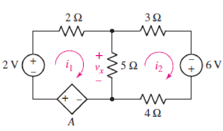
FIGURE 4.24
Expert Solution & Answer
Want to see the full answer?
Check out a sample textbook solution
Students have asked these similar questions
a. Using KVL, complete the working equations for the clipping circuits shown in Fig. 4.11 for both positive and
negative half-cycles of the input.
Simple Parallel Clippers (ldeal Diodles)
Biased Parallel Clippers tldeal Diodes)
Figure 4.11 Clipping Circuits (Parallel)
Problem 4.10
Figure
601
$40.0
8011201
1 of 1
Use the node-voltage method to find us in the circuit(Egure 1)if i=57 A and i=14 A
Express your answer with the appropriate units.
21
Part B
Submit Request Answer
μÅ
Value
123
Value
→
Use the node-voltage method to find t in the circut
Express your answer with the appropriate units.
Units
Units
?
?
Assuming the diodes to be ideal, find the values of I and V in the circuits of Fig. 4.6.
+ 10 V
+ 10 V
10 k2
5 k0
+
Z Dz
D, SZ
V.
V.
B
B
5 ΚΩ
10 kn
- 10 V
- 10 V
(a)
(b)
Chapter 4 Solutions
Loose Leaf for Engineering Circuit Analysis Format: Loose-leaf
Ch. 4.1 - For the circuit of Fig. 4.3, determine the nodal...Ch. 4.1 - For the circuit of Fig. 4.5, compute the voltage...Ch. 4.1 - For the circuit of Fig. 4.8, determine the nodal...Ch. 4.2 - For the circuit of Fig. 4.11, compute the voltage...Ch. 4.3 - Determine i1 and i2 in the circuit in Fig. 4.19....Ch. 4.3 - Determine i1 and i2 in the circuit of Fig 4.21....Ch. 4.3 - Determine i1 in the circuit of Fig. 4.24 if the...Ch. 4.4 - Determine the current i1 in the circuit of Fig....Ch. 4.4 - Determine v3 in the circuit of Fig. 4.28. FIGURE...Ch. 4 - Solve the following systems of equations: (a) 2v2 ...
Ch. 4 - (a) Solve the following system of equations:...Ch. 4 - (a) Solve the following system of equations:...Ch. 4 - Correct (and verify by running) the following...Ch. 4 - In the circuit of Fig. 4.35, determine the current...Ch. 4 - Calculate the power dissipated in the 1 resistor...Ch. 4 - For the circuit in Fig. 4.37, determine the value...Ch. 4 - With the assistance of nodal analysis, determine...Ch. 4 - Prob. 9ECh. 4 - For the circuit of Fig. 4.40, determine the value...Ch. 4 - Use nodal analysis to find vP in the circuit shown...Ch. 4 - Prob. 12ECh. 4 - Prob. 13ECh. 4 - Determine a numerical value for each nodal voltage...Ch. 4 - Prob. 15ECh. 4 - Using nodal analysis as appropriate, determine the...Ch. 4 - Prob. 17ECh. 4 - Determine the nodal voltages as labeled in Fig....Ch. 4 - Prob. 19ECh. 4 - Prob. 20ECh. 4 - Employing supernode/nodal analysis techniques as...Ch. 4 - Prob. 22ECh. 4 - Prob. 23ECh. 4 - Prob. 24ECh. 4 - Repeat Exercise 23 for the case where the 12 V...Ch. 4 - Prob. 26ECh. 4 - Prob. 27ECh. 4 - Determine the value of k that will result in vx...Ch. 4 - Prob. 29ECh. 4 - Prob. 30ECh. 4 - Prob. 31ECh. 4 - Determine the currents flowing out of the positive...Ch. 4 - Obtain numerical values for the two mesh currents...Ch. 4 - Use mesh analysis as appropriate to determine the...Ch. 4 - Prob. 35ECh. 4 - Prob. 36ECh. 4 - Find the unknown voltage vx in the circuit in Fig....Ch. 4 - Prob. 38ECh. 4 - Prob. 39ECh. 4 - Determine the power dissipated in the 4 resistor...Ch. 4 - (a) Employ mesh analysis to determine the power...Ch. 4 - Define three clockwise mesh currents for the...Ch. 4 - Prob. 43ECh. 4 - Prob. 44ECh. 4 - Prob. 45ECh. 4 - Prob. 46ECh. 4 - Prob. 47ECh. 4 - Prob. 48ECh. 4 - Prob. 49ECh. 4 - Prob. 50ECh. 4 - Prob. 51ECh. 4 - Prob. 52ECh. 4 - For the circuit represented schematically in Fig....Ch. 4 - The circuit of Fig. 4.80 is modified such that the...Ch. 4 - The circuit of Fig. 4.81 contains three sources....Ch. 4 - Solve for the voltage vx as labeled in the circuit...Ch. 4 - Consider the five-source circuit of Fig. 4.83....Ch. 4 - Replace the dependent voltage source in the...Ch. 4 - After studying the circuit of Fig. 4.84, determine...Ch. 4 - Prob. 60ECh. 4 - Employ LTspice (or similar CAD tool) to verify the...Ch. 4 - Employ LTspice (or similar CAD tool) to verify the...Ch. 4 - Employ LTspice (or similar CAD tool) to verify the...Ch. 4 - Verify numerical values for each nodal voltage in...Ch. 4 - Prob. 65ECh. 4 - Prob. 66ECh. 4 - Prob. 67ECh. 4 - Prob. 68ECh. 4 - Prob. 69ECh. 4 - (a) Under what circumstances does the presence of...Ch. 4 - Referring to Fig. 4.88, (a) determine whether...Ch. 4 - Consider the LED circuit containing a red, green,...Ch. 4 - The LED circuit in Fig. 4.89 is used to mix colors...Ch. 4 - A light-sensing circuit is in Fig. 4.90, including...Ch. 4 - Use SPICE to analyze the circuit in Exercise 74 by...
Knowledge Booster


Learn more about
Need a deep-dive on the concept behind this application? Look no further. Learn more about this topic, electrical-engineering and related others by exploring similar questions and additional content below.Similar questions
- Consider the circuit in Figure 4. a) Find the Thevenin equivalent of the network connected to the capacitor C1. b) Find the mathematical equations for the transient behavior of voltage vc(t) and the current ic(t) following the closing of the switch. c) Determine the value of voltage vc at t = 100 ms. %3D TC LOSE = 0 R1 TK V1 15V 6K R2 LIK R3 C1 R4 0. 3Karrow_forwardQ4/ A) For the circuit shown below, calculate the current i, the conductance G, and the power P. 30 V (+ 5 k2arrow_forward4.47.3 In the circuit shown in the image below, if R1 = 38 Q, R2 = 37 Q, and 1 A, determine the Norton current IN (in A) for its Norton equivalent circuit observed = 1.9 between terminals a and b. R2 R1 +. 20lv Please pay attention: the numbers may change since they are randomized. Your answer should keep 1 place after the decimal point. Your Answer: Answerarrow_forward
- 4.47.3 In the circuit shown in the image below, if R1 = 38 Q, R2 = 37 Q, and 1 A, determine the Norton current IN (in A) for its Norton equivalent circuit observed = 1.9 between terminals a and b. R2 R1 201v o b Please pay attention: the numbers may change since they are randomized. Your answer should keep 1 place after the decimal point. Your Answer: Answerarrow_forwardQ4: A 6V battery delivers 10MA to three resistors in parallel, R1 1kN, R2= 2kN, R3= Rx. Calculate : a) Current in Rx, that is Ix. [Ans: 1mA] b) Power dissipated by Rx and R1. c) Resistance ratio "*/R1• [Ans: 6mw, 36mw] [Ans: /1] 14 d) Current ratio [Ans: /1]arrow_forward4.54.2 In the circuit shown in the image below, if Ro = 1.3 k2, Rx= 53 2, and V 1.7 V, determine the Thevenin resistance RTh (in 2) for its Thevenin equivalent circuit observed between terminals a and b. Ro 401 2Vx Rx V, ob Please pay attention: the numbers may change since they are randomized. Your answer should keep 1 place after the decimal point. Your Answer: Answerarrow_forward
- Q4(b)) Figure 1(b) shows the schematic diagram of a potentiometer for the measurement of displacement. i) Detemine the relationship between output voltage V, and the input voltage V, , as a function of x and the ratio of total displacement if the load resistance is R. Solve for the output voltage, V at 0.75 reading of the potentiometer for the value of the resistance ratio Rp/R= 2%. Rp(1-x) Rp Rp(0arrow_forward(a) Simplify the circuit shown in Figure Q4 (a) into single voltage source by applying source transformation and determine the current, io. 3 A 6 A 20 V Figure Q4 (a)arrow_forwardConsider the circuit in Figure 4. a) Find the Thevenin equivalent of the network connected to the capacitor C1. b) Find the mathematical equations for the transient behavior of voltage ve(t) and the current ic(t) following the closing of the switch. c) Determine the value of voltage ve at t=100 ms. TCLOSE = 0 R1 1. 21 5k 30 V VI 3k R2 2k R3 C1 33UF R4 1k 0.arrow_forward
- x 32 1, 6 3. 2.5:10 V -I Ri Vs Ri Pea ) hka tau Enketahei InyO Q4. Determine the voltage V and the current I for the network in Figure Q4. 82 30 V Figure Q4 82 Q5. For the circuit of Figure Q5, find I, V1 and power, P absorbed by the 4 2 resistor. 1.52 22 + V1 P = ? 15 V 2.5 2 050 22 1.52 Figure Q5 For the network in Figure Q6, a. Find currents Is, 12 and l6 b. Find voltages V1 and Vs Find the power delivered to the 3 k 2 resistor. Q6. C. 9 k2 R4 Is R5 6 k2 Is 28 V R1 R2 + V; R3 10.4 k2 R6 V1 12 k2 12 k2 3 k2 Figure Q6 4.arrow_forwardExercise: Sketch the output (Vo) for the circuit of Fig. 4-8 for the input (Vi) shown. Assume ideal diodes. Vi 15 A 0 T/2 -15 t + V₁ Eo 317 R₁ m Fig. (4-8) D₂ E÷WVE₂+10V D₁ R₂ Voarrow_forwardSubject:Circuits IShow your solutions help me please so that i can learn tooarrow_forward
arrow_back_ios
SEE MORE QUESTIONS
arrow_forward_ios
Recommended textbooks for you
 Introductory Circuit Analysis (13th Edition)Electrical EngineeringISBN:9780133923605Author:Robert L. BoylestadPublisher:PEARSON
 Delmar's Standard Textbook Of ElectricityElectrical EngineeringISBN:9781337900348Author:Stephen L. HermanPublisher:Cengage Learning
 Programmable Logic ControllersElectrical EngineeringISBN:9780073373843Author:Frank D. PetruzellaPublisher:McGraw-Hill Education
 Fundamentals of Electric CircuitsElectrical EngineeringISBN:9780078028229Author:Charles K Alexander, Matthew SadikuPublisher:McGraw-Hill Education
 Electric Circuits. (11th Edition)Electrical EngineeringISBN:9780134746968Author:James W. Nilsson, Susan RiedelPublisher:PEARSON
 Engineering ElectromagneticsElectrical EngineeringISBN:9780078028151Author:Hayt, William H. (william Hart), Jr, BUCK, John A.Publisher:Mcgraw-hill Education,
Introductory Circuit Analysis (13th Edition)
Electrical Engineering
ISBN:9780133923605
Author:Robert L. Boylestad
Publisher:PEARSON
Delmar's Standard Textbook Of Electricity
Electrical Engineering
ISBN:9781337900348
Author:Stephen L. Herman
Publisher:Cengage Learning
Programmable Logic Controllers
Electrical Engineering
ISBN:9780073373843
Author:Frank D. Petruzella
Publisher:McGraw-Hill Education
Fundamentals of Electric Circuits
Electrical Engineering
ISBN:9780078028229
Author:Charles K Alexander, Matthew Sadiku
Publisher:McGraw-Hill Education
Electric Circuits. (11th Edition)
Electrical Engineering
ISBN:9780134746968
Author:James W. Nilsson, Susan Riedel
Publisher:PEARSON
Engineering Electromagnetics
Electrical Engineering
ISBN:9780078028151
Author:Hayt, William H. (william Hart), Jr, BUCK, John A.
Publisher:Mcgraw-hill Education,
Mesh Current Problems in Circuit Analysis - Electrical Circuits Crash Course - Beginners Electronics; Author: Math and Science;https://www.youtube.com/watch?v=DYg8B-ElK0s;License: Standard Youtube License