
Loose Leaf for Engineering Circuit Analysis Format: Loose-leaf
9th Edition
ISBN: 9781259989452
Author: Hayt
Publisher: Mcgraw Hill Publishers
expand_more
expand_more
format_list_bulleted
Concept explainers
Videos
Textbook Question
Chapter 4, Problem 6E
Calculate the power dissipated in the 1 Ω resistor of Fig. 4.36.
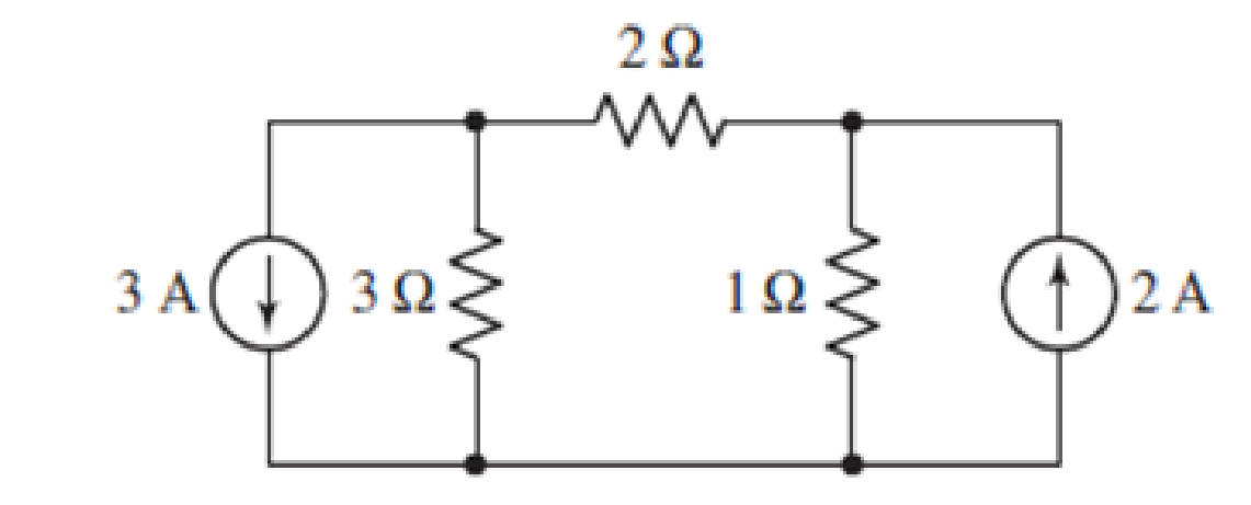
FIGURE 4.36
Expert Solution & Answer
Want to see the full answer?
Check out a sample textbook solution
Students have asked these similar questions
22. Referring to the circuit of Fig. 4.48, obtain a numerical value for the power
supplied by the 1 V source.
6 A
4 V
14 N
ΤΩ
3 V
4 A (1
20
FIGURE 4.48
25. Consider the circuit of Fig. 4.51. Determine the current labeled ij.
0.5i
20
3 V
2 A
I FIGURE 4.51
Obtain numerical values for the two mesh currents ij and iz in the circuit
shown in Fig. 4.61.
32
5 V
iz
12 V
14 2
Given the information appearing in Fig. 4.74, determine:
(a) Ic.
(b) Rc.
(c) Rg-
(d) VCE-
12 V
Ic
RC
RB
O Vc = 6 V
VCE B= 80
IB= 40 µA
Chapter 4 Solutions
Loose Leaf for Engineering Circuit Analysis Format: Loose-leaf
Ch. 4.1 - For the circuit of Fig. 4.3, determine the nodal...Ch. 4.1 - For the circuit of Fig. 4.5, compute the voltage...Ch. 4.1 - For the circuit of Fig. 4.8, determine the nodal...Ch. 4.2 - For the circuit of Fig. 4.11, compute the voltage...Ch. 4.3 - Determine i1 and i2 in the circuit in Fig. 4.19....Ch. 4.3 - Determine i1 and i2 in the circuit of Fig 4.21....Ch. 4.3 - Determine i1 in the circuit of Fig. 4.24 if the...Ch. 4.4 - Determine the current i1 in the circuit of Fig....Ch. 4.4 - Determine v3 in the circuit of Fig. 4.28. FIGURE...Ch. 4 - Solve the following systems of equations: (a) 2v2 ...
Ch. 4 - (a) Solve the following system of equations:...Ch. 4 - (a) Solve the following system of equations:...Ch. 4 - Correct (and verify by running) the following...Ch. 4 - In the circuit of Fig. 4.35, determine the current...Ch. 4 - Calculate the power dissipated in the 1 resistor...Ch. 4 - For the circuit in Fig. 4.37, determine the value...Ch. 4 - With the assistance of nodal analysis, determine...Ch. 4 - Prob. 9ECh. 4 - For the circuit of Fig. 4.40, determine the value...Ch. 4 - Use nodal analysis to find vP in the circuit shown...Ch. 4 - Prob. 12ECh. 4 - Prob. 13ECh. 4 - Determine a numerical value for each nodal voltage...Ch. 4 - Prob. 15ECh. 4 - Using nodal analysis as appropriate, determine the...Ch. 4 - Prob. 17ECh. 4 - Determine the nodal voltages as labeled in Fig....Ch. 4 - Prob. 19ECh. 4 - Prob. 20ECh. 4 - Employing supernode/nodal analysis techniques as...Ch. 4 - Prob. 22ECh. 4 - Prob. 23ECh. 4 - Prob. 24ECh. 4 - Repeat Exercise 23 for the case where the 12 V...Ch. 4 - Prob. 26ECh. 4 - Prob. 27ECh. 4 - Determine the value of k that will result in vx...Ch. 4 - Prob. 29ECh. 4 - Prob. 30ECh. 4 - Prob. 31ECh. 4 - Determine the currents flowing out of the positive...Ch. 4 - Obtain numerical values for the two mesh currents...Ch. 4 - Use mesh analysis as appropriate to determine the...Ch. 4 - Prob. 35ECh. 4 - Prob. 36ECh. 4 - Find the unknown voltage vx in the circuit in Fig....Ch. 4 - Prob. 38ECh. 4 - Prob. 39ECh. 4 - Determine the power dissipated in the 4 resistor...Ch. 4 - (a) Employ mesh analysis to determine the power...Ch. 4 - Define three clockwise mesh currents for the...Ch. 4 - Prob. 43ECh. 4 - Prob. 44ECh. 4 - Prob. 45ECh. 4 - Prob. 46ECh. 4 - Prob. 47ECh. 4 - Prob. 48ECh. 4 - Prob. 49ECh. 4 - Prob. 50ECh. 4 - Prob. 51ECh. 4 - Prob. 52ECh. 4 - For the circuit represented schematically in Fig....Ch. 4 - The circuit of Fig. 4.80 is modified such that the...Ch. 4 - The circuit of Fig. 4.81 contains three sources....Ch. 4 - Solve for the voltage vx as labeled in the circuit...Ch. 4 - Consider the five-source circuit of Fig. 4.83....Ch. 4 - Replace the dependent voltage source in the...Ch. 4 - After studying the circuit of Fig. 4.84, determine...Ch. 4 - Prob. 60ECh. 4 - Employ LTspice (or similar CAD tool) to verify the...Ch. 4 - Employ LTspice (or similar CAD tool) to verify the...Ch. 4 - Employ LTspice (or similar CAD tool) to verify the...Ch. 4 - Verify numerical values for each nodal voltage in...Ch. 4 - Prob. 65ECh. 4 - Prob. 66ECh. 4 - Prob. 67ECh. 4 - Prob. 68ECh. 4 - Prob. 69ECh. 4 - (a) Under what circumstances does the presence of...Ch. 4 - Referring to Fig. 4.88, (a) determine whether...Ch. 4 - Consider the LED circuit containing a red, green,...Ch. 4 - The LED circuit in Fig. 4.89 is used to mix colors...Ch. 4 - A light-sensing circuit is in Fig. 4.90, including...Ch. 4 - Use SPICE to analyze the circuit in Exercise 74 by...
Knowledge Booster


Learn more about
Need a deep-dive on the concept behind this application? Look no further. Learn more about this topic, electrical-engineering and related others by exploring similar questions and additional content below.Similar questions
- 1. Calculate the Vnu R, and find the Thevenin equivalent circuit of the circuits in Fig. 4.6. 4.7 ka 2.7 ko 15 ko 3AO 12 v 3.9 2.7 3.3 10 V 15 ko ko (a) (b) Figure 4.6 ww wwarrow_forwardFor Fig. 4.37, calculate the voltage gain. Given that: 8m = 4 mA/V, rd=45 k2, R₂ = 20 k2, and R = 100 MS2 | + VDD Vin ww RG 100 ΜΩ www ww RD = 20 k Rs C₂ Cs Voarrow_forwardO Paye view A Read aloud V Draw E Hiyhlight O Erase 6 of 15 HW1 4.11 Use the superposition principle to find i, and v, in the circuit of Fig. 4.79. ps 10 Ω 20 Ω 6 A ( 40 Q 4i, 30 V 10:44 PM O Type here to search ^ 立用曲ENG 3/22/2021arrow_forward
- Q5 Draw the output voltage waveform for each circuit in Fig. 4.30 with respect the input. Show voltage levels. +1 V +1 V 0- -I V +2 V Vunmuy = 18 V Vrtmna = 110 V %3D -2 V (a) (b)arrow_forwardUsing Thevenin's theorem, find the equivalent circuit to the left Fig. 4.30. Then find Practice: 9.1 the terminals in the circuit in 12 V 2A 40 10 VTh=6 V, RTh = 3 2, i = 1.5 A. Answer: %3D %3Darrow_forwardQ5 Draw the output voltage waveform for each circuit in Fig. 4.30 with respect to the input. Show voltage levels. +I V +1 V 0- -I V +2 V Vutmery = 18 V -2 V (a) (b)arrow_forward
- D LMH_chapter2-part2-homework. X + O File | C:/Users/DELL/Downloads/LMH_chapter2-part2-homework.pdf D Page view A Read aloud V Draw E Highlight O Erase 11 of 15 HW10 *4.61 Obtain the Thevenin and Norton equivalent circuits A at terminals a-b of the circuit in Fig. 4.127. ML 2Ω o a 6Ω 12 V (+ I) 12 V 6 Q 2 2 12 V 11:16 PM O Type here to search ^ a D 4) E ENG 3/22/2021arrow_forward4.26 Use source transformation to find /, in the circu Fig. 4.94. 50 ЗА 40 6 A 20 20 V Figure 4.94arrow_forward47. For the circuit of Fig. 4.76, determine the value of resistor X if iz = 2.273 A. %3D 22 19 7V 7 Varrow_forward
- (Example 4.8) Determine all node voltages and branch currents assuming = 100. Assume Active +5 V 100 ΚΩ www +10 V 2 ΚΩarrow_forward47. For the circuit of Fig. 4.76, determine the value of resistor X if iz = 2.273 A. iz 30 19 7 V 7 Varrow_forward2.7 ka 2.2 kn 3. Consider the value of R, for maximum power transfer in the circuit of Fig. 4.7 and calculate the maximum power. 1.5 ka RL Figure 4.7arrow_forward
arrow_back_ios
SEE MORE QUESTIONS
arrow_forward_ios
Recommended textbooks for you
 Introductory Circuit Analysis (13th Edition)Electrical EngineeringISBN:9780133923605Author:Robert L. BoylestadPublisher:PEARSON
 Delmar's Standard Textbook Of ElectricityElectrical EngineeringISBN:9781337900348Author:Stephen L. HermanPublisher:Cengage Learning
 Programmable Logic ControllersElectrical EngineeringISBN:9780073373843Author:Frank D. PetruzellaPublisher:McGraw-Hill Education
 Fundamentals of Electric CircuitsElectrical EngineeringISBN:9780078028229Author:Charles K Alexander, Matthew SadikuPublisher:McGraw-Hill Education
 Electric Circuits. (11th Edition)Electrical EngineeringISBN:9780134746968Author:James W. Nilsson, Susan RiedelPublisher:PEARSON
 Engineering ElectromagneticsElectrical EngineeringISBN:9780078028151Author:Hayt, William H. (william Hart), Jr, BUCK, John A.Publisher:Mcgraw-hill Education,
Introductory Circuit Analysis (13th Edition)
Electrical Engineering
ISBN:9780133923605
Author:Robert L. Boylestad
Publisher:PEARSON
Delmar's Standard Textbook Of Electricity
Electrical Engineering
ISBN:9781337900348
Author:Stephen L. Herman
Publisher:Cengage Learning
Programmable Logic Controllers
Electrical Engineering
ISBN:9780073373843
Author:Frank D. Petruzella
Publisher:McGraw-Hill Education
Fundamentals of Electric Circuits
Electrical Engineering
ISBN:9780078028229
Author:Charles K Alexander, Matthew Sadiku
Publisher:McGraw-Hill Education
Electric Circuits. (11th Edition)
Electrical Engineering
ISBN:9780134746968
Author:James W. Nilsson, Susan Riedel
Publisher:PEARSON
Engineering Electromagnetics
Electrical Engineering
ISBN:9780078028151
Author:Hayt, William H. (william Hart), Jr, BUCK, John A.
Publisher:Mcgraw-hill Education,
Norton's Theorem and Thevenin's Theorem - Electrical Circuit Analysis; Author: The Organic Chemistry Tutor;https://www.youtube.com/watch?v=-kkvqr1wSwA;License: Standard Youtube License