
Loose Leaf for Engineering Circuit Analysis Format: Loose-leaf
9th Edition
ISBN: 9781259989452
Author: Hayt
Publisher: Mcgraw Hill Publishers
expand_more
expand_more
format_list_bulleted
Concept explainers
Videos
Textbook Question
Chapter 4, Problem 54E
The circuit of Fig. 4.80 is modified such that the 3 A source is replaced by a 3 V source whose positive reference terminal is connected to the 7Ω resistor.
- (a) Determine the number of nodal equations required to determine i5.
- (b) Alternatively, how many mesh equations would be required?
- (c) Would your preferred analysis method change if only the voltage across the 7 Ω resistor were needed? Explain.
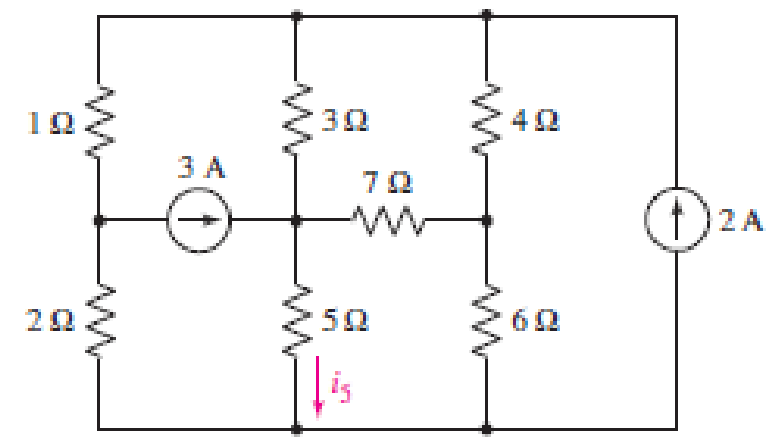
FIGURE 4.80
Expert Solution & Answer
Want to see the full answer?
Check out a sample textbook solution
Students have asked these similar questions
(True/False) It is safe to connect a 2002 resistor rated at 3/4W in parallel with a 10V
source rated 10W.
Select one:
O True
O False
4:34 PM
Find the current in the 1 Q resistor of *
the circuit below using Norton's
theorem.
24 V
6 A
8 A
5 A
O7A
252
www
8 A
20 V
120 Ω
452
www
A voltage divider and its Thevenin's
equivalent circuit is shown below.
What will be the value of Eth and
Rth?
802->>
485.2
K/S
1092 ≤12
Eth
Rth
*
89
If we want to connect a voltage source with
two resistors (either in series or in parallel)
then voltage drop across the resistor R1
and the voltage across the resistor R2 ( if
R1= R,= 10N) will be the same whether
they are connected in series or in parallel.
Select one:
O True
False
< o O
Chapter 4 Solutions
Loose Leaf for Engineering Circuit Analysis Format: Loose-leaf
Ch. 4.1 - For the circuit of Fig. 4.3, determine the nodal...Ch. 4.1 - For the circuit of Fig. 4.5, compute the voltage...Ch. 4.1 - For the circuit of Fig. 4.8, determine the nodal...Ch. 4.2 - For the circuit of Fig. 4.11, compute the voltage...Ch. 4.3 - Determine i1 and i2 in the circuit in Fig. 4.19....Ch. 4.3 - Determine i1 and i2 in the circuit of Fig 4.21....Ch. 4.3 - Determine i1 in the circuit of Fig. 4.24 if the...Ch. 4.4 - Determine the current i1 in the circuit of Fig....Ch. 4.4 - Determine v3 in the circuit of Fig. 4.28. FIGURE...Ch. 4 - Solve the following systems of equations: (a) 2v2 ...
Ch. 4 - (a) Solve the following system of equations:...Ch. 4 - (a) Solve the following system of equations:...Ch. 4 - Correct (and verify by running) the following...Ch. 4 - In the circuit of Fig. 4.35, determine the current...Ch. 4 - Calculate the power dissipated in the 1 resistor...Ch. 4 - For the circuit in Fig. 4.37, determine the value...Ch. 4 - With the assistance of nodal analysis, determine...Ch. 4 - Prob. 9ECh. 4 - For the circuit of Fig. 4.40, determine the value...Ch. 4 - Use nodal analysis to find vP in the circuit shown...Ch. 4 - Prob. 12ECh. 4 - Prob. 13ECh. 4 - Determine a numerical value for each nodal voltage...Ch. 4 - Prob. 15ECh. 4 - Using nodal analysis as appropriate, determine the...Ch. 4 - Prob. 17ECh. 4 - Determine the nodal voltages as labeled in Fig....Ch. 4 - Prob. 19ECh. 4 - Prob. 20ECh. 4 - Employing supernode/nodal analysis techniques as...Ch. 4 - Prob. 22ECh. 4 - Prob. 23ECh. 4 - Prob. 24ECh. 4 - Repeat Exercise 23 for the case where the 12 V...Ch. 4 - Prob. 26ECh. 4 - Prob. 27ECh. 4 - Determine the value of k that will result in vx...Ch. 4 - Prob. 29ECh. 4 - Prob. 30ECh. 4 - Prob. 31ECh. 4 - Determine the currents flowing out of the positive...Ch. 4 - Obtain numerical values for the two mesh currents...Ch. 4 - Use mesh analysis as appropriate to determine the...Ch. 4 - Prob. 35ECh. 4 - Prob. 36ECh. 4 - Find the unknown voltage vx in the circuit in Fig....Ch. 4 - Prob. 38ECh. 4 - Prob. 39ECh. 4 - Determine the power dissipated in the 4 resistor...Ch. 4 - (a) Employ mesh analysis to determine the power...Ch. 4 - Define three clockwise mesh currents for the...Ch. 4 - Prob. 43ECh. 4 - Prob. 44ECh. 4 - Prob. 45ECh. 4 - Prob. 46ECh. 4 - Prob. 47ECh. 4 - Prob. 48ECh. 4 - Prob. 49ECh. 4 - Prob. 50ECh. 4 - Prob. 51ECh. 4 - Prob. 52ECh. 4 - For the circuit represented schematically in Fig....Ch. 4 - The circuit of Fig. 4.80 is modified such that the...Ch. 4 - The circuit of Fig. 4.81 contains three sources....Ch. 4 - Solve for the voltage vx as labeled in the circuit...Ch. 4 - Consider the five-source circuit of Fig. 4.83....Ch. 4 - Replace the dependent voltage source in the...Ch. 4 - After studying the circuit of Fig. 4.84, determine...Ch. 4 - Prob. 60ECh. 4 - Employ LTspice (or similar CAD tool) to verify the...Ch. 4 - Employ LTspice (or similar CAD tool) to verify the...Ch. 4 - Employ LTspice (or similar CAD tool) to verify the...Ch. 4 - Verify numerical values for each nodal voltage in...Ch. 4 - Prob. 65ECh. 4 - Prob. 66ECh. 4 - Prob. 67ECh. 4 - Prob. 68ECh. 4 - Prob. 69ECh. 4 - (a) Under what circumstances does the presence of...Ch. 4 - Referring to Fig. 4.88, (a) determine whether...Ch. 4 - Consider the LED circuit containing a red, green,...Ch. 4 - The LED circuit in Fig. 4.89 is used to mix colors...Ch. 4 - A light-sensing circuit is in Fig. 4.90, including...Ch. 4 - Use SPICE to analyze the circuit in Exercise 74 by...
Knowledge Booster


Learn more about
Need a deep-dive on the concept behind this application? Look no further. Learn more about this topic, electrical-engineering and related others by exploring similar questions and additional content below.Similar questions
- Q4. For the below circuit, determine: (a) The Thevenin equivalent circuit as seen from a-b. (b) The value of R and Ps for maximum power transfer to R₁ 40V 402 m 292 m 1210 a b R₁arrow_forwardThe resistance R for the circuit is: * R 600 W + 40 V – 40 V (+ 60 V 9.3330 4000 40 O 0.250arrow_forwardConsider the given circuit where /x = 5.5 A. 7 V 392 2 A 30 I Using as many source transformations and element combination techniques as required, simplify the given circuit so that it contains only the 7 V source, a single resistor, and one other voltage source. (You must provide an answer before moving on to the next part.) The simplified circuit contains the 7 V source, a single resistor of Q, and another voltage source of V.arrow_forward
- The equivalent resistance in the infinite ladder network shown in figure, is Re R www 2R am R R The value of Re/R is R R ** www ∞arrow_forwardUsing nodal method, find the value of v(t). *Express 5H as current source for iL (0) *Express 0.1F with voltage source for Vc (0)arrow_forwardSolve for R equivalent or Total Resistance of the following circuit: (please draw also, thank you!)arrow_forward
- Calculate each of the circuit parameters for the provided circuit RT v1 v2 v3 v4 v5 Va Is Is I1 I2 I3 I4 I5 Vb PR1 PR2 PR3 PR4 PR5 VCarrow_forwardDesign a voltage divider circuit (with a bleeder current of 20mA) that operates from a 500V source to supply the following loads: a) 400V @ 100mA b) 200V @ 50mA c) 100V @ 30mAarrow_forwardWhich of the following is an accurate statement? (A An ideal current source do not contribute any amount of current (B) Superposition theorem can be used only for multiple source. The current in an element is the sum of the individual effect of each source. D An ideal voltage source act as short circuit when suppressed.arrow_forward
- c) Analyse the steady-state voltage vo(t) of the circuit in Figure Q4(b) if the input voltage is given by: v;(t) = 7.5 cos(2t - 122°) +2.2 cos(6t – 102°) +1.3 cos(10t – 97°) + 0.91 cos(14t – 95°) + ... V Show your answer for the first four terms of the output voltage, Vo(t).arrow_forwardQ4: Obtain the Thevenin equivalent circuit at terminals a-b for the circuit in figure shown below: 5 A 10% + 10 492 292 www-oa barrow_forward10 mA 1.5 ΚΩ M 1kΩ www 2 ΚΩ 20 mA RL W Q4) For the circuit shown above, find the following: a) The Thevenin equivalent circuit as seen by the load resistance "RL" b) The Norton equivalent circuit as seen by the load resistance "RL" c) The load resistance "R₁" that would absorb maximum power d) The value of the maximum power absorbed by the load found in (c)arrow_forward
arrow_back_ios
SEE MORE QUESTIONS
arrow_forward_ios
Recommended textbooks for you
 Introductory Circuit Analysis (13th Edition)Electrical EngineeringISBN:9780133923605Author:Robert L. BoylestadPublisher:PEARSON
 Delmar's Standard Textbook Of ElectricityElectrical EngineeringISBN:9781337900348Author:Stephen L. HermanPublisher:Cengage Learning
 Programmable Logic ControllersElectrical EngineeringISBN:9780073373843Author:Frank D. PetruzellaPublisher:McGraw-Hill Education
 Fundamentals of Electric CircuitsElectrical EngineeringISBN:9780078028229Author:Charles K Alexander, Matthew SadikuPublisher:McGraw-Hill Education
 Electric Circuits. (11th Edition)Electrical EngineeringISBN:9780134746968Author:James W. Nilsson, Susan RiedelPublisher:PEARSON
 Engineering ElectromagneticsElectrical EngineeringISBN:9780078028151Author:Hayt, William H. (william Hart), Jr, BUCK, John A.Publisher:Mcgraw-hill Education,
Introductory Circuit Analysis (13th Edition)
Electrical Engineering
ISBN:9780133923605
Author:Robert L. Boylestad
Publisher:PEARSON
Delmar's Standard Textbook Of Electricity
Electrical Engineering
ISBN:9781337900348
Author:Stephen L. Herman
Publisher:Cengage Learning
Programmable Logic Controllers
Electrical Engineering
ISBN:9780073373843
Author:Frank D. Petruzella
Publisher:McGraw-Hill Education
Fundamentals of Electric Circuits
Electrical Engineering
ISBN:9780078028229
Author:Charles K Alexander, Matthew Sadiku
Publisher:McGraw-Hill Education
Electric Circuits. (11th Edition)
Electrical Engineering
ISBN:9780134746968
Author:James W. Nilsson, Susan Riedel
Publisher:PEARSON
Engineering Electromagnetics
Electrical Engineering
ISBN:9780078028151
Author:Hayt, William H. (william Hart), Jr, BUCK, John A.
Publisher:Mcgraw-hill Education,
Norton's Theorem and Thevenin's Theorem - Electrical Circuit Analysis; Author: The Organic Chemistry Tutor;https://www.youtube.com/watch?v=-kkvqr1wSwA;License: Standard Youtube License