
Loose Leaf for Engineering Circuit Analysis Format: Loose-leaf
9th Edition
ISBN: 9781259989452
Author: Hayt
Publisher: Mcgraw Hill Publishers
expand_more
expand_more
format_list_bulleted
Videos
Textbook Question
Chapter 4, Problem 71E
Referring to Fig. 4.88, (a) determine whether nodal or mesh analysis is more appropriate in determining i2 if element A is replaced with a short circuit, then carry out the analysis. (b) Verify your answer with an appropriate LTspice simulation. Submit a properly labeled schematic along with the answer highlighted.
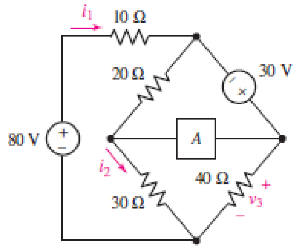
■ FIGURE 4.88
Expert Solution & Answer
Want to see the full answer?
Check out a sample textbook solution
Students have asked these similar questions
(a) Write the minimum set of equations in symbolic expression(without solving the circuit) using node-voltage method
(b)Write the minimum set of equations in symbolic expression(without solving the circuit) using mesh-current method
(c)Based on the numerical values given in the figure, determine the voltage and current in each resistor using either (a) or (b)
How many the:
nodes
paths
loops
meshes
branches
Referring to the network in the Figure 1
(a) Apply node analysis to all unknown nodes in Figure 1. Based on this analysis, specify all the equations that you have obtained.
(b) Based on the equations obtained above, is there any possible solution? State the reason for your answer. If the solution is impossible, suggest a simple addition orchange to the network above, and prove that your suggestion is valid.
Chapter 4 Solutions
Loose Leaf for Engineering Circuit Analysis Format: Loose-leaf
Ch. 4.1 - For the circuit of Fig. 4.3, determine the nodal...Ch. 4.1 - For the circuit of Fig. 4.5, compute the voltage...Ch. 4.1 - For the circuit of Fig. 4.8, determine the nodal...Ch. 4.2 - For the circuit of Fig. 4.11, compute the voltage...Ch. 4.3 - Determine i1 and i2 in the circuit in Fig. 4.19....Ch. 4.3 - Determine i1 and i2 in the circuit of Fig 4.21....Ch. 4.3 - Determine i1 in the circuit of Fig. 4.24 if the...Ch. 4.4 - Determine the current i1 in the circuit of Fig....Ch. 4.4 - Determine v3 in the circuit of Fig. 4.28. FIGURE...Ch. 4 - Solve the following systems of equations: (a) 2v2 ...
Ch. 4 - (a) Solve the following system of equations:...Ch. 4 - (a) Solve the following system of equations:...Ch. 4 - Correct (and verify by running) the following...Ch. 4 - In the circuit of Fig. 4.35, determine the current...Ch. 4 - Calculate the power dissipated in the 1 resistor...Ch. 4 - For the circuit in Fig. 4.37, determine the value...Ch. 4 - With the assistance of nodal analysis, determine...Ch. 4 - Prob. 9ECh. 4 - For the circuit of Fig. 4.40, determine the value...Ch. 4 - Use nodal analysis to find vP in the circuit shown...Ch. 4 - Prob. 12ECh. 4 - Prob. 13ECh. 4 - Determine a numerical value for each nodal voltage...Ch. 4 - Prob. 15ECh. 4 - Using nodal analysis as appropriate, determine the...Ch. 4 - Prob. 17ECh. 4 - Determine the nodal voltages as labeled in Fig....Ch. 4 - Prob. 19ECh. 4 - Prob. 20ECh. 4 - Employing supernode/nodal analysis techniques as...Ch. 4 - Prob. 22ECh. 4 - Prob. 23ECh. 4 - Prob. 24ECh. 4 - Repeat Exercise 23 for the case where the 12 V...Ch. 4 - Prob. 26ECh. 4 - Prob. 27ECh. 4 - Determine the value of k that will result in vx...Ch. 4 - Prob. 29ECh. 4 - Prob. 30ECh. 4 - Prob. 31ECh. 4 - Determine the currents flowing out of the positive...Ch. 4 - Obtain numerical values for the two mesh currents...Ch. 4 - Use mesh analysis as appropriate to determine the...Ch. 4 - Prob. 35ECh. 4 - Prob. 36ECh. 4 - Find the unknown voltage vx in the circuit in Fig....Ch. 4 - Prob. 38ECh. 4 - Prob. 39ECh. 4 - Determine the power dissipated in the 4 resistor...Ch. 4 - (a) Employ mesh analysis to determine the power...Ch. 4 - Define three clockwise mesh currents for the...Ch. 4 - Prob. 43ECh. 4 - Prob. 44ECh. 4 - Prob. 45ECh. 4 - Prob. 46ECh. 4 - Prob. 47ECh. 4 - Prob. 48ECh. 4 - Prob. 49ECh. 4 - Prob. 50ECh. 4 - Prob. 51ECh. 4 - Prob. 52ECh. 4 - For the circuit represented schematically in Fig....Ch. 4 - The circuit of Fig. 4.80 is modified such that the...Ch. 4 - The circuit of Fig. 4.81 contains three sources....Ch. 4 - Solve for the voltage vx as labeled in the circuit...Ch. 4 - Consider the five-source circuit of Fig. 4.83....Ch. 4 - Replace the dependent voltage source in the...Ch. 4 - After studying the circuit of Fig. 4.84, determine...Ch. 4 - Prob. 60ECh. 4 - Employ LTspice (or similar CAD tool) to verify the...Ch. 4 - Employ LTspice (or similar CAD tool) to verify the...Ch. 4 - Employ LTspice (or similar CAD tool) to verify the...Ch. 4 - Verify numerical values for each nodal voltage in...Ch. 4 - Prob. 65ECh. 4 - Prob. 66ECh. 4 - Prob. 67ECh. 4 - Prob. 68ECh. 4 - Prob. 69ECh. 4 - (a) Under what circumstances does the presence of...Ch. 4 - Referring to Fig. 4.88, (a) determine whether...Ch. 4 - Consider the LED circuit containing a red, green,...Ch. 4 - The LED circuit in Fig. 4.89 is used to mix colors...Ch. 4 - A light-sensing circuit is in Fig. 4.90, including...Ch. 4 - Use SPICE to analyze the circuit in Exercise 74 by...
Knowledge Booster


Learn more about
Need a deep-dive on the concept behind this application? Look no further. Learn more about this topic, electrical-engineering and related others by exploring similar questions and additional content below.Similar questions
- answer all sub partsarrow_forwardnodes paths loops meshes branchesarrow_forwardWrite the system of nodal equations via nodal analysis for this circuit. Make it very detailed explaining the steps and also how nodal analysis should generally be performed in circuits such as this one. And how do we know how many kcl equations we should do ( it's general formula) thank youarrow_forward
- Repeat solving figure 2, using Mesh equation methodarrow_forwardUse the mesh current method to find the mesh currents in the circuit of Figure 6. Assume that R₁ = 10 , R₂ = 5, V₁ = 2 V, V₂ = 1 V and Is = 2 A V₁ Copyright © McGraw Hill LLC. All rights reserved. No reproduction or distribution without the prior written consent of McGraw Hill LLC. (+1) V₂ ww R₁ R₂ ww Isarrow_forwardDirections: The illustration below shows the components of a simple circuit diagram. Choose from the choices on the left the best term or description that will match each component and its function. Write your answer on the prescribed box. • Battery Component: Function: Load Switch • Wire Converts electrical Component: Component: energy into heat, light, or mechanical Function: Function: energy • Completes or breaks circuit by allowing or stopping current from flowing • Provides a route for Component Function: the current to flow through • Supplies electrical energy that causes current flowarrow_forward
- TITLE: Superposition Theorem DESCRIPTION: In this project, you will need to find the validity and the power behind the Superposition theorem. You need to search about the theorem, find its definition and apply it to a problem to find the concept behind the theorem. Show a step by step solution for an electrical circuit problem two times (Solve a circuit two times finding voltage or current): 1- Without using superposition theorem (You can use any method (Nodal, Mesh, ..etc) 2- Using superposition theorem. Your solutions should be well organized, answering the questions properly in detail and in a step by step solution. Write your findings and write your conclusion about the superposition theorem.arrow_forwardBreadboard Projects Propose a SIMPLE PROJECT with the use of Basic Electronic Components and Define why you’ve chosen/decided to propose that project? What is itsimportance? Requirements :Title of the Project:Its Importance:List of Components:Breadboard Layout:arrow_forwarda. Consider the following circuit in Figure 6 to find VR1 , Iz and IR5 by using nodal analysis b. listand explain in detail any three advantages of nodal analysis.(prove each point with example)arrow_forward
- SUBJECT: INDUSTRIAL ELECTRONICS TOPIC: Power Supply Using LM 317 & LM337 NOTE: ANSWER THE FOLLOWING QUESTIONS AND EXPLAIN AND EXPOUND YOUR ANSWER! MAKE SURE THE ANSWER IS CORRECT TO RATE YOU HIGHLY FOR THE ANSWER. ANSWER THE TABLE AND OTHER QUESTIONS. THANK YOU! answer with correct, PLEASE FOLLOW INSTRUCTIONS ANSWER IT IN CORRECT & Explain THANKS Make a (3) titles about this project: A. B. C. Make abstract about this project: ABSTRACT - [ is a self-contained, short, and powerful statement that describes a larger work. Abstracts cannot contain equations, figures, or tables.] Make an introduction about this project that contains the (1) Background of the Project (2) Objective of the Project, (3) Scope and Limitation of the Project INTRODUCTIONarrow_forwardPlease show the complete solution. Thank you so much Voltage Multipliers (electronics)arrow_forward4. Differentiate between the accuracy of the Wheatstone bridge and Kelvin Double bridge for the respective resistance measurement. 5. Signify the bridge to be used for the measurement of a test resistor having a value around 50 kQ? 6. In contrast, the unbalanced Wheatstone bridge is often used for measurement of different physical quantities. 6.1 Determine the condition(s) for unbalanced Wheatstone bridge 6.2 State and briefly explain what are physical quantities can be measured using an unbalanced Wheatstone bridge.arrow_forward
arrow_back_ios
SEE MORE QUESTIONS
arrow_forward_ios
Recommended textbooks for you
 Introductory Circuit Analysis (13th Edition)Electrical EngineeringISBN:9780133923605Author:Robert L. BoylestadPublisher:PEARSON
 Delmar's Standard Textbook Of ElectricityElectrical EngineeringISBN:9781337900348Author:Stephen L. HermanPublisher:Cengage Learning
 Programmable Logic ControllersElectrical EngineeringISBN:9780073373843Author:Frank D. PetruzellaPublisher:McGraw-Hill Education
 Fundamentals of Electric CircuitsElectrical EngineeringISBN:9780078028229Author:Charles K Alexander, Matthew SadikuPublisher:McGraw-Hill Education
 Electric Circuits. (11th Edition)Electrical EngineeringISBN:9780134746968Author:James W. Nilsson, Susan RiedelPublisher:PEARSON
 Engineering ElectromagneticsElectrical EngineeringISBN:9780078028151Author:Hayt, William H. (william Hart), Jr, BUCK, John A.Publisher:Mcgraw-hill Education,
Introductory Circuit Analysis (13th Edition)
Electrical Engineering
ISBN:9780133923605
Author:Robert L. Boylestad
Publisher:PEARSON
Delmar's Standard Textbook Of Electricity
Electrical Engineering
ISBN:9781337900348
Author:Stephen L. Herman
Publisher:Cengage Learning
Programmable Logic Controllers
Electrical Engineering
ISBN:9780073373843
Author:Frank D. Petruzella
Publisher:McGraw-Hill Education
Fundamentals of Electric Circuits
Electrical Engineering
ISBN:9780078028229
Author:Charles K Alexander, Matthew Sadiku
Publisher:McGraw-Hill Education
Electric Circuits. (11th Edition)
Electrical Engineering
ISBN:9780134746968
Author:James W. Nilsson, Susan Riedel
Publisher:PEARSON
Engineering Electromagnetics
Electrical Engineering
ISBN:9780078028151
Author:Hayt, William H. (william Hart), Jr, BUCK, John A.
Publisher:Mcgraw-hill Education,
[1.2] 8086 Microprocessor Architecture; Author: ThinkX Academy;https://www.youtube.com/watch?v=XX9rDGTBGgQ;License: Standard Youtube License