
Concept explainers
Videos
Use SPICE to analyze the circuit in Exercise 74 by doing the following. (a) Simulate the circuit for varying values of Rpot to balance the circuit at 500 lux, where Rlight = 200 Ω. It is helpful to use a parameter sweep by defining a variable such as {potentiometer} (including the curly brackets) in the value for Rpot, and a SPICE directive such as .step param potentiometer 150 250 2 to step the variable from 150 to 250 in steps of 2. (b) If the resistance of the photoresistor decreases by 2% for for a light increase to 600 lux, use SPICE to find the resulting output voltage Vout.
74. A light-sensing circuit is in Fig. 4.90, including a resistor that changes value under illumination (photoresistor Rlight) and a variable resistor (potentiometer Rpot). The circuit is in the Wheatstone bridge configuration such that a “balanced” condition results in Vout = 0 for a defined value of incident light and a corresponding value for Rlight. (a) Derive an algebraic expression for Vout in terms of RS, R1, R2, Rlight, and Rpot. (b) Using the numerical values given in the circuit, calculate the value of Rpot required to balance the circuit at 500 lux, where Rlight = 200 Ω. (c) If the resistance of the photoresistor decreases by 2% for a light increase to 600 lux (and assuming the resistance change with light is linear), what will the light level be if you measure Vout = 150 mV?
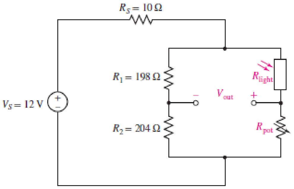
■ FIGURE 4.90
Want to see the full answer?
Check out a sample textbook solution
Chapter 4 Solutions
Loose Leaf for Engineering Circuit Analysis Format: Loose-leaf


- 1. LED flashlights use "white" LEDs which have a diode voltage drop of 4.0V. An LED flashlight has the circuit illustrated and will run off of several AAA batteries that have a 1.5 VDC rating. a. What is the minimum number of AAA cells are needed to turn on the flashlight. 4/1.5 = 2.65 /3 b. Would you arrange the batteries in parallel or in series? Series a. What series resistor will give the specified LED current? (67 K 70 L b. What is the power dissipated by the resistor you selected in part a? Vdd fritzing 2. In the previous diagram for an LED circuit, the power supply is a 9V battery and we are using a Red LED whose voltage drop is 2V. The specification sheet for the LED recommends that the "ON" current should be 10 milliamps. c. What is the power dissipated in the LED? R + LED V 1arrow_forwardINSTRUCTIONS: Solve the following problems. Show and COMPLETE solutions. Draw all CIRCUIT DIAGRAMS or the equivalent circuit (dummy circuit) as the case may be. Write your solutions on sheet/s of short bond paper. A battery is to consist of 20 identical cells. The emf of each cell is 1.5 V and the internal resistance is 0.20 ohm. This battery will be used to supply power to a 10 ohm lamp. Determine the current on the lamp if:1. The 20 cells are connected in series 2. The 20 cells are connected in parallel 3. The 20 cells are arranged 5 cells in series in 4 parallel rows.arrow_forwardWrite neat and answer all questions. 1. Given the following circuit diagram derive the following • Input equation State table State diagram Clock D CRarrow_forward
- Consider the circuit shown in the figure. A Q-point value for Ic between a minimum of 4 mA and a maximum of 5 mA is required. Assume that resistor values are constant and that 8 ranges from 105 to 310. It is desired for Rp to have the largest possible value while meeting Part A the other constraints. Determine the value of RR. (Figure 1) Express your answer to three significant figures and include the appropriate units. HẢ Rp = Omega Submit Previous Answers Request Answer Figure < 1 of 1 +15 V Part B Determine the value of RE. 1 k2 Express your answer to three significant figures and include the appropriate units. RB VBEQ = 0.7 V HẢ ? 5 V RE RE = Omega Submit Previous Answers Request Answerarrow_forward3. Based on an old quiz problem related to half-wave rectifièr design. You may need your design if we have cold weather this winter. for charging your 12 VDC car battery. You are to design a battery eharger for safe operation in a damp garage environment to use RI Current Ling Resor R1 TXI Fuse 12 Vot Car Bater Metal Case Design specifications include: (a) Input is a 110rms VAC. (Vp=110x v2) at 60 Hz from a three wire service that meets the National Electrical Code. (b) Output is a nominal 12 volts VDC at the cathode of the diode. (c) Specify a resistor, R, to limit the maximum battery charging current to 10 amperes into the 12 volt car battery assuming the battery is completely dead (0 volts) when you first connect the charger. A not uncommon occurrence over the last two weeks of sub-zero temperatures. (d) There is no ripple voltage design specification. Explain why this is unnecessary in this application. (e) The battery charger case is metal. (f) Assume a diode with VF= 0.7 V (g)…arrow_forward1. ) Minimize the following DFA using a. Huffman algorithm using Distinct table. For each step draw a separate Distinct table. 0, 1 1 q1 q2 q4 qo 93 1 95 1. 1.arrow_forward
- Consider the circuit shown in the figure. A Q-point value for Ic between a minimum of 4 mA and a maximum of 5 mA is required. Assume that resistor values are constant and that 3 ranges from 100 to 330. It is desired for RB to have the largest possible value while meeting the other constraints. (Figure 1) 1 of 1 +15 V VBEQ=0.7 V Figure 5 V RB RE 1 ks Determine the value of R.B. Express your answer to three significant figures and include the appropriate units. ► View Available Hint(s) Submit Previous Answers Part B Determine the value of RE. Express your answer to three significant figures and include the appropriate units. ► View Available Hint(s) μA ? RE= Value Unitsarrow_forward(b) Prove the circuit in Figure Q.5 can perform the operation of adder/subtractor by completing Table Q.5. -Sub FA FA FA FA Figure Q.5 Table Q.5 B[3:0] Sub A[3:0] C4 S[3:0] Operation 0111 1000 1 0111 1000arrow_forwardPart A: A multi-range ammeter is required to measure the current in a certain network. A PMMC instrument has connected as an Ayrton shunt with a four resistor across PMMC. The resistance values are R1 = 0.0060, R2 = 0.0650, R3 = 4.00 and R4 %3D =10.00. The PMMC has Rm = 1kQ and FSD = 50µA. %3D a. Draw the circuit for the multi-range Ayrton shunt. b. Calculate the four current ranges of the ammeter. c. What is the main advantage of Ayrton shunt ammeter compared to parallel type. d. Briefly explain how this device can be calibrated. * Note: Show all calculation details. Part B: The measurement of the voltage from a prototype of a 20V DC power supply were captured by 8 times as shown in the following table: Number 1 6 Voltage (V) 18.5 19.8 20.2 19.9 20.0 20.1 19.7 18.9 Determine the following: 1. the arithmetic mean, 2. the standard deviation of the readings, 3. the probable error. 4. If the voltmeter that used to carry the measurements has an error of 0.5%; calculate the total error in…arrow_forward
- Tutorial Problems As 1. For the circuit in Figure, find (a) 80a 200 100 fthe value of the supply voltage V (b) the value of currentarrow_forwardThe following are the readings taken while conducting an experiment on a wind turbine. what will be the value of open circuit voltage, if the short circuit current is 0.472 A, Maximum power point voltage is 5.32 V, Maximum power point current is 0.111 A and the fill factor is 0.599? Select one: a. 2080 mV b. 2.08 mV c. 8020 V d. 80.2 Varrow_forwardA moving-coil instrument gives full-scale deflection with 25 mA. The resistance of the coil is 5 ohm. It is required to convert this meter into an ammeter to read up to 5 A. Find (a) the resistance of the shunt to be connected in parallel with the meter, and (b) the value of series resistance for the above meter to read up to a voltage of 20 V.arrow_forward
 Introductory Circuit Analysis (13th Edition)Electrical EngineeringISBN:9780133923605Author:Robert L. BoylestadPublisher:PEARSON
 Delmar's Standard Textbook Of ElectricityElectrical EngineeringISBN:9781337900348Author:Stephen L. HermanPublisher:Cengage Learning
 Programmable Logic ControllersElectrical EngineeringISBN:9780073373843Author:Frank D. PetruzellaPublisher:McGraw-Hill Education
 Fundamentals of Electric CircuitsElectrical EngineeringISBN:9780078028229Author:Charles K Alexander, Matthew SadikuPublisher:McGraw-Hill Education
 Electric Circuits. (11th Edition)Electrical EngineeringISBN:9780134746968Author:James W. Nilsson, Susan RiedelPublisher:PEARSON
 Engineering ElectromagneticsElectrical EngineeringISBN:9780078028151Author:Hayt, William H. (william Hart), Jr, BUCK, John A.Publisher:Mcgraw-hill Education,