
Loose Leaf for Engineering Circuit Analysis Format: Loose-leaf
9th Edition
ISBN: 9781259989452
Author: Hayt
Publisher: Mcgraw Hill Publishers
expand_more
expand_more
format_list_bulleted
Concept explainers
Videos
Textbook Question
Chapter 4.2, Problem 4P
For the circuit of Fig. 4.11, compute the voltage across each current source.
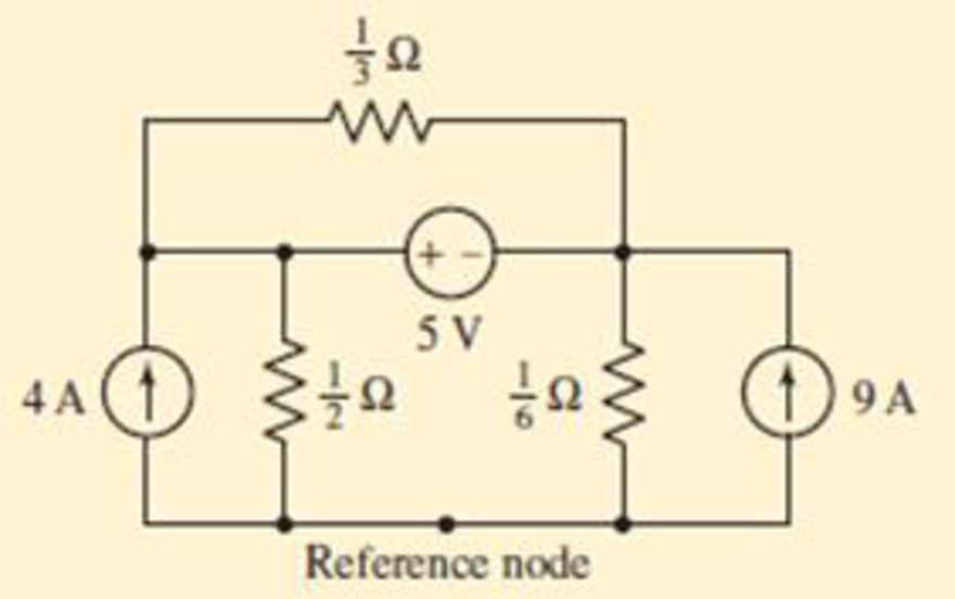
FIGURE 4.11
Expert Solution & Answer
Want to see the full answer?
Check out a sample textbook solution
Students have asked these similar questions
4.1.Part A: Ohm's law
This part aims at checking and proving Ohm's law. Using the fixed 5 V output from the power supply,
the 1k, 2k2 and 5k resistors, and considering all the possible unique circuit combinations with
these 3 resistors only, conduct the followings:
1. Before the lab session and manually
a) design and manually sketch your various circuits using the fixed 5 V power supply (i.e. put
the resistors in various parallel or series combinations),
b) calculate the current (immediately after the power supply) for all your circuits and find the
current and the power dissipated in each of the 3 resistors,
c) rank the circuits from maximum to minimum current observed immediately after the power
supply, and
d) prepare your report and have it with you electronically at the time of your lab session.
2. Before the lab session, and using the LushProjects simulator (see above URL)
a) make simulation files and simulate all your circuits,
b) check and compare the results with the manual…
Q4/ A)
For the circuit shown below, calculate the current i, the conductance G, and the power P.
30 V (+
5 k2
Value of IB is 4.81A. Prove this using mesh-current analysis. Show diagram and label solution.
Chapter 4 Solutions
Loose Leaf for Engineering Circuit Analysis Format: Loose-leaf
Ch. 4.1 - For the circuit of Fig. 4.3, determine the nodal...Ch. 4.1 - For the circuit of Fig. 4.5, compute the voltage...Ch. 4.1 - For the circuit of Fig. 4.8, determine the nodal...Ch. 4.2 - For the circuit of Fig. 4.11, compute the voltage...Ch. 4.3 - Determine i1 and i2 in the circuit in Fig. 4.19....Ch. 4.3 - Determine i1 and i2 in the circuit of Fig 4.21....Ch. 4.3 - Determine i1 in the circuit of Fig. 4.24 if the...Ch. 4.4 - Determine the current i1 in the circuit of Fig....Ch. 4.4 - Determine v3 in the circuit of Fig. 4.28. FIGURE...Ch. 4 - Solve the following systems of equations: (a) 2v2 ...
Ch. 4 - (a) Solve the following system of equations:...Ch. 4 - (a) Solve the following system of equations:...Ch. 4 - Correct (and verify by running) the following...Ch. 4 - In the circuit of Fig. 4.35, determine the current...Ch. 4 - Calculate the power dissipated in the 1 resistor...Ch. 4 - For the circuit in Fig. 4.37, determine the value...Ch. 4 - With the assistance of nodal analysis, determine...Ch. 4 - Prob. 9ECh. 4 - For the circuit of Fig. 4.40, determine the value...Ch. 4 - Use nodal analysis to find vP in the circuit shown...Ch. 4 - Prob. 12ECh. 4 - Prob. 13ECh. 4 - Determine a numerical value for each nodal voltage...Ch. 4 - Prob. 15ECh. 4 - Using nodal analysis as appropriate, determine the...Ch. 4 - Prob. 17ECh. 4 - Determine the nodal voltages as labeled in Fig....Ch. 4 - Prob. 19ECh. 4 - Prob. 20ECh. 4 - Employing supernode/nodal analysis techniques as...Ch. 4 - Prob. 22ECh. 4 - Prob. 23ECh. 4 - Prob. 24ECh. 4 - Repeat Exercise 23 for the case where the 12 V...Ch. 4 - Prob. 26ECh. 4 - Prob. 27ECh. 4 - Determine the value of k that will result in vx...Ch. 4 - Prob. 29ECh. 4 - Prob. 30ECh. 4 - Prob. 31ECh. 4 - Determine the currents flowing out of the positive...Ch. 4 - Obtain numerical values for the two mesh currents...Ch. 4 - Use mesh analysis as appropriate to determine the...Ch. 4 - Prob. 35ECh. 4 - Prob. 36ECh. 4 - Find the unknown voltage vx in the circuit in Fig....Ch. 4 - Prob. 38ECh. 4 - Prob. 39ECh. 4 - Determine the power dissipated in the 4 resistor...Ch. 4 - (a) Employ mesh analysis to determine the power...Ch. 4 - Define three clockwise mesh currents for the...Ch. 4 - Prob. 43ECh. 4 - Prob. 44ECh. 4 - Prob. 45ECh. 4 - Prob. 46ECh. 4 - Prob. 47ECh. 4 - Prob. 48ECh. 4 - Prob. 49ECh. 4 - Prob. 50ECh. 4 - Prob. 51ECh. 4 - Prob. 52ECh. 4 - For the circuit represented schematically in Fig....Ch. 4 - The circuit of Fig. 4.80 is modified such that the...Ch. 4 - The circuit of Fig. 4.81 contains three sources....Ch. 4 - Solve for the voltage vx as labeled in the circuit...Ch. 4 - Consider the five-source circuit of Fig. 4.83....Ch. 4 - Replace the dependent voltage source in the...Ch. 4 - After studying the circuit of Fig. 4.84, determine...Ch. 4 - Prob. 60ECh. 4 - Employ LTspice (or similar CAD tool) to verify the...Ch. 4 - Employ LTspice (or similar CAD tool) to verify the...Ch. 4 - Employ LTspice (or similar CAD tool) to verify the...Ch. 4 - Verify numerical values for each nodal voltage in...Ch. 4 - Prob. 65ECh. 4 - Prob. 66ECh. 4 - Prob. 67ECh. 4 - Prob. 68ECh. 4 - Prob. 69ECh. 4 - (a) Under what circumstances does the presence of...Ch. 4 - Referring to Fig. 4.88, (a) determine whether...Ch. 4 - Consider the LED circuit containing a red, green,...Ch. 4 - The LED circuit in Fig. 4.89 is used to mix colors...Ch. 4 - A light-sensing circuit is in Fig. 4.90, including...Ch. 4 - Use SPICE to analyze the circuit in Exercise 74 by...
Knowledge Booster


Learn more about
Need a deep-dive on the concept behind this application? Look no further. Learn more about this topic, electrical-engineering and related others by exploring similar questions and additional content below.Similar questions
- 4.4 For the circuit of Fig. 4.10, compute the voltage across cách current source. Ans: 5.375 V, 375 mV. 5 V ) 9 A 4 A Reference nodearrow_forwardAssuming the diodes to be ideal, find the values of I and V in the circuits of Fig. 4.6. + 10 V + 10 V 10 k2 5 k0 + Z Dz D, SZ V. V. B B 5 ΚΩ 10 kn - 10 V - 10 V (a) (b)arrow_forward1. For the fixed-bias configuration of Fig. 4.118, determine: a. IBg' 16 V b. Icg c. VCEg Ico 1.8 k22 510 kQ2 VB IBQ Vc VCEQ B=120 VEarrow_forward
- 1 11:08 O Yo 4G 74% LTE Tutorial-04.do... 22. Referring to the circuit of Fig. 4.48, obtain a numerical value for the power supplied by the 1 V source. 6 A 4 V 14 2 3 V 320 330 20 I FIGURE 4.48 25. Consider the circuit of Fig. 4.51. Determine the current labeled ij. 0.5i, IFIGURE 4.51 42. Determine values for the three mesh currents of Fig. 4.67. IFIGURE 4.67 47 Thonoh careful annlication of the sunermesh technieme ohtain valnes for all ... IIarrow_forward(a) Simplify the circuit shown in Figure Q4 (a) into single voltage source by applying source transformation and determine the current, io. 3 A 6 A 20 V Figure Q4 (a)arrow_forwardExample 4.2 Assuming the diodes to be ideal, find the values of I and V in the circuits of Fig. 4.6. + 10 V + 10 V 10 kn 5 kN | !p2 字D。 DSZ ,立 文D V V B B 5 kn 10 kn - 10 V - 10 V (a) (b)arrow_forward
- Q4: A 6V battery delivers 10MA to three resistors in parallel, R1 1kN, R2= 2kN, R3= Rx. Calculate : a) Current in Rx, that is Ix. [Ans: 1mA] b) Power dissipated by Rx and R1. c) Resistance ratio "*/R1• [Ans: 6mw, 36mw] [Ans: /1] 14 d) Current ratio [Ans: /1]arrow_forwardQ2 / In circuit switching network, mention the available paths to go from node A to node B, then choose one path taking in consideration that Routing Algorithm concerns the shortest path. 4. 10arrow_forward(Example 4.8) Determine all node voltages and branch currents assuming = 100. Assume Active +5 V 100 ΚΩ www +10 V 2 ΚΩarrow_forward
- 1. For the fixed -bias configuration of Fig. 4.73, detetmine 16 V. 2.7K2 3470K2 (b) Ice C) VCEQ d) Vc e) Vo f) VE YB VCER B=901 VE IBQarrow_forward112 ELECTRICAL CIRCUITS-DIRECT CURRENT * 18. The wiring arrangement shown in Fig. 4:26 is known as an Edison three-wire system. For the values indicated, calculate (a) E, E, and Eo; (b) the power delivered to loads A, B, and C. . 0.150 (+) E-120 Load A EA 50 amp 0.15n Load C Ec 20 amp ww (+) Load B Ez=120 EB 30 amp www 0.15 N F1o. 428 Edison three-wire system for Prob. 16.arrow_forward4.15 The limiter circuit of Fig. 4.5(a) is connected with V+ = 3 V and R = 100 2. The diode data sheet specifies a maximum reverse voltage of 10 V and maximum forward current of 50 mA. What are the maximum and minimum voltages that may be safely applied at vj? A Hide Answer -7 V≤v≤8V You might not be able to send or receive mail. To continue using Gmail, clean up space or get more storage. Figure 4.5 (a) + DI R www (a) EVarrow_forward
arrow_back_ios
SEE MORE QUESTIONS
arrow_forward_ios
Recommended textbooks for you
 Introductory Circuit Analysis (13th Edition)Electrical EngineeringISBN:9780133923605Author:Robert L. BoylestadPublisher:PEARSON
 Delmar's Standard Textbook Of ElectricityElectrical EngineeringISBN:9781337900348Author:Stephen L. HermanPublisher:Cengage Learning
 Programmable Logic ControllersElectrical EngineeringISBN:9780073373843Author:Frank D. PetruzellaPublisher:McGraw-Hill Education
 Fundamentals of Electric CircuitsElectrical EngineeringISBN:9780078028229Author:Charles K Alexander, Matthew SadikuPublisher:McGraw-Hill Education
 Electric Circuits. (11th Edition)Electrical EngineeringISBN:9780134746968Author:James W. Nilsson, Susan RiedelPublisher:PEARSON
 Engineering ElectromagneticsElectrical EngineeringISBN:9780078028151Author:Hayt, William H. (william Hart), Jr, BUCK, John A.Publisher:Mcgraw-hill Education,
Introductory Circuit Analysis (13th Edition)
Electrical Engineering
ISBN:9780133923605
Author:Robert L. Boylestad
Publisher:PEARSON
Delmar's Standard Textbook Of Electricity
Electrical Engineering
ISBN:9781337900348
Author:Stephen L. Herman
Publisher:Cengage Learning
Programmable Logic Controllers
Electrical Engineering
ISBN:9780073373843
Author:Frank D. Petruzella
Publisher:McGraw-Hill Education
Fundamentals of Electric Circuits
Electrical Engineering
ISBN:9780078028229
Author:Charles K Alexander, Matthew Sadiku
Publisher:McGraw-Hill Education
Electric Circuits. (11th Edition)
Electrical Engineering
ISBN:9780134746968
Author:James W. Nilsson, Susan Riedel
Publisher:PEARSON
Engineering Electromagnetics
Electrical Engineering
ISBN:9780078028151
Author:Hayt, William H. (william Hart), Jr, BUCK, John A.
Publisher:Mcgraw-hill Education,
Norton's Theorem and Thevenin's Theorem - Electrical Circuit Analysis; Author: The Organic Chemistry Tutor;https://www.youtube.com/watch?v=-kkvqr1wSwA;License: Standard Youtube License