
Loose Leaf for Engineering Circuit Analysis Format: Loose-leaf
9th Edition
ISBN: 9781259989452
Author: Hayt
Publisher: Mcgraw Hill Publishers
expand_more
expand_more
format_list_bulleted
Videos
Textbook Question
Chapter 5, Problem 22E
(a) With the assistance of source transformations, transform the two voltage sources in Fig. 5.66 into appropriate current sources. (b) Using your new circuit, calculate the power dissipated in the 7 Ω resistor. (c) Verify your solution by simulating both circuits.
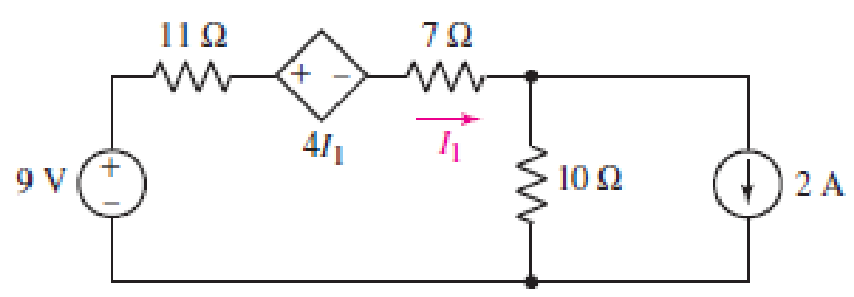
■ FIGURE 5.66
Expert Solution & Answer
Want to see the full answer?
Check out a sample textbook solution
Students have asked these similar questions
Find the current across the resistor 5 52 while the switch
S is open for a long time.
A) (A)
B)(A)
C) (A)
3 V
192
ΖΩΣ
D) (A)
26
3ΩΣ
5 V
E) (A)
4 V
www
:552
Determine the Equivalent Resistance (Rab) of the circuit. ( please provide illustrations/drawings it is needed for our solutions)
Q17. For the circuit shown in Figure 5.23
calculate (a) the value of resistor Rx such
that the total power dissipated in the circuit
is 2.5kW, and (b) the current flowing in
each of the four resistors.
4 Rq=15 2
a A3=38 2
R2=10 2
Rx
12
14
V2²
250 V
Chapter 5 Solutions
Loose Leaf for Engineering Circuit Analysis Format: Loose-leaf
Ch. 5.1 - For the circuit of Fig. 5.4, use superposition to...Ch. 5.2 - For the circuit of Fig. 5.7, use superposition to...Ch. 5.2 - For the circuit of Fig. 5.18, compute the current...Ch. 5.2 - For the circuit of Fig. 5.20, compute the voltage...Ch. 5.3 - Using repeated source transformations, determine...Ch. 5.3 - Use Thvenins theorem to find the current through...Ch. 5.3 - Determine the Thvenin and Norton equivalents of...Ch. 5.3 - Find the Thvenin equivalent for the network of...Ch. 5.3 - Find the Thvenin equivalent for the network of...Ch. 5.4 - Consider the circuit of Fig. 5.43. FIGURE 5.43...
Ch. 5.5 - Prob. 11PCh. 5 - Linear systems are so easy to work with that...Ch. 5 - Prob. 2ECh. 5 - Prob. 3ECh. 5 - (a) Employ superposition to determine the current...Ch. 5 - (a) Using superposition to consider each source...Ch. 5 - (a) Determine the individual contributions of each...Ch. 5 - (a) Determine the individual contributions of each...Ch. 5 - After studying the circuit of Fig. 5.53, change...Ch. 5 - Consider the three circuits shown in Fig. 5.54....Ch. 5 - (a) Using superposition, determine the voltage...Ch. 5 - Employ superposition principles to obtain a value...Ch. 5 - (a) Employ superposition to determine the...Ch. 5 - Perform an appropriate source transformation on...Ch. 5 - (a) For the circuit of Fig. 5.59, plot iL versus...Ch. 5 - Determine the current labeled I in the circuit of...Ch. 5 - Verify that the power absorbed by the 7 resistor...Ch. 5 - (a) Determine the current labeled i in the circuit...Ch. 5 - (a) Using repeated source transformations, reduce...Ch. 5 - Prob. 19ECh. 5 - (a) Making use of repeated source transformations,...Ch. 5 - Prob. 21ECh. 5 - (a) With the assistance of source transformations,...Ch. 5 - For the circuit in Fig. 5.67 transform all...Ch. 5 - Prob. 24ECh. 5 - (a) Referring to Fig. 5.69, determine the Thevenin...Ch. 5 - (a) With respect to the circuit depicted in Fig....Ch. 5 - (a) Obtain the Norton equivalent of the network...Ch. 5 - (a) Determine the Thevenin equivalent of the...Ch. 5 - Referring to the circuit of Fig. 5.71: (a)...Ch. 5 - Prob. 30ECh. 5 - (a) Employ Thvenins theorem to obtain a...Ch. 5 - Prob. 32ECh. 5 - Determine the Norton equivalent of the circuit...Ch. 5 - For the circuit of Fig. 5.75: (a) Employ Nortons...Ch. 5 - (a) Obtain a value for the Thvenin equivalent...Ch. 5 - Prob. 36ECh. 5 - Obtain a value for the Thvenin equivalent...Ch. 5 - With regard to the network depicted in Fig. 5.79,...Ch. 5 - Determine the Thvenin and Norton equivalents of...Ch. 5 - Determine the Norton equivalent of the circuit...Ch. 5 - Prob. 41ECh. 5 - Determine the Thvenin and Norton equivalents of...Ch. 5 - Prob. 43ECh. 5 - Prob. 44ECh. 5 - Prob. 45ECh. 5 - (a) For the simple circuit of Fig. 5.87, find the...Ch. 5 - For the circuit drawn in Fig. 5.88, (a) determine...Ch. 5 - Study the circuit of Fig. 5.89. (a) Determine the...Ch. 5 - Prob. 49ECh. 5 - Prob. 50ECh. 5 - With reference to the circuit of Fig. 5.91, (a)...Ch. 5 - Prob. 52ECh. 5 - Select a value for RL in Fig. 5.93 such that it...Ch. 5 - Determine what value of resistance would absorb...Ch. 5 - Derive the equations required to convert from a...Ch. 5 - Convert the - (or "-") connected networks in Fig....Ch. 5 - Convert the Y-(or T-) connected networks in Fig....Ch. 5 - For the network of Fig. 5.97, select a value of R...Ch. 5 - For the network of Fig. 5.98, select a value of R...Ch. 5 - Prob. 60ECh. 5 - Calculate Rin as indicated in Fig.5.100. FIGURE...Ch. 5 - Employ Y conversion techniques as appropriate to...Ch. 5 - Prob. 63ECh. 5 - (a) Use appropriate techniques to obtain both the...Ch. 5 - (a) For the network in Fig. 5.104, replace the...Ch. 5 - Prob. 66ECh. 5 - Prob. 67ECh. 5 - A 2.57 load is connected between terminals a and...Ch. 5 - A load resistor is connected across the open...Ch. 5 - A backup is required for the circuit depicted in...Ch. 5 - (a) Explain in general terms how source...Ch. 5 - The load resistor in Fig. 5.108 can safely...Ch. 5 - Prob. 74ECh. 5 - As part of a security system, a very thin 100 ...Ch. 5 - With respect to the circuit in Fig. 5.90, (a)...
Knowledge Booster


Learn more about
Need a deep-dive on the concept behind this application? Look no further. Learn more about this topic, electrical-engineering and related others by exploring similar questions and additional content below.Similar questions
- Given the circuit below. The current through the 100 resistor in the circuit below is 8.0 mA. Determine the 2002 5.0 (2 [www] 10:2 a) total resistance b) total current c) total voltage 30 2 www wwww 5.002 4002arrow_forwardLMH_chapter3-part 1-homework [Protected View] PowerPoint ĐĂNG PHẠM HỒNG File Home Insert Design Transitions Animations Slide Show Review View Help Tell me what you want to do & Share 4 HW16 5.13 Find u, and i, in the circuit of Fig. 5.52. HW18 10 ka 1vO 100 ka 90 ka 10 ka 5.20 In the circuit of Fig. 5.59, calculate v, of v; = 0. 50 k2 8 kQ HW17 ww 5.14 Determine the output voltage v, in the circuit of 5.53. 10 ka 2 k2 10 ka 20 ka 4 k2 4 k2 Sma O 5 kQ www ww 6. 9 V HW18 5.20 In the circuit of Fig. 5.59, calculate v, of v; = 0. 8 ka 4 ka 4 ka ww 7 HW19 3.24 In the circuit shown in Fig. 5.62, find k in the voltage tYansfer flunction ,- b, R. 6. ww-arrow_forward6. a) Use the mesh-current method to write a complete set of equations that could be used to solve this circuit. Do not simplify the circuit. Do not attempt to solve or simplify your equations. Define all variables. b) Compare the number of equations required using the node-voltage method and the mesh current method, for this circuit. Which method requires fewer equations? 32[0] 24[Q] 28[Q] 11[O]ix 31[Q) 30[0] | 2[V] 33[Q] i 34[Q] 35[0] 3[A] 38[0] 29[0] 10[O]i 4[V] Vr 36[2] 37[0] 6[A] 5[V] 25[0]arrow_forward
- 5:05 For the circuit shown, the value of the curr... For the circuit shown, the value of the current flow through R₁ would be: R5 Mc Graw Hill #H F1 4.5 mA A @ с R4 Multiple Choice F2 3mA 1.5 mA. 20 # R6 V F3 9 V M 00 $ A R1 4 V F4 1.25 mA A) 1.5 mA. R3 % * Co 8 F8arrow_forwardTwo 60.0 Ω resistors are connected in parallel and this parallel arrangement is then connected in series with a 30.0 Ω resistor. The combination is placed across a 120. V potential difference. a.) Draw a diagram of the circuit. b.) What is the equivalent resistance of the parallel portion of the circuit? c.) What is the equivalent resistance for the entire circuit? d.) What is the total current in the circuit? e.) What is the voltage drop across the 30.0 Ω resistor? f.) What is the voltage drop across the parallel portion of the circuit?arrow_forwardAnswer the following problem (Kindly provide a CLEAR and COMPLETE solution)*Note: Please answer it ASAP if possible*arrow_forward
- A point at which two or more elements have a common connection is called a mesh. Select one: O True Falsearrow_forwardKindly solve what is ask and provide complete solution so that I can understand. Also, I want a handwritten solution. Thank you so much.:arrow_forwardQuestion 48 Study the circuit of Fig. 5.89. a) Determine the Norton equivalent connected to resistor Rout. b) Select a value for Rout such that maximum power will be delivered to it. 4 A FIGURE 5.89 ΚΩ 3 V 2 V 2 kΩ Routarrow_forward
- Can someone please help me out and provide the full solution and answer for this example, I need it as my reviewer. Thank you so much!arrow_forward6:06 A e-learning.hct.edu.om Question: A group of Students from UTAS (Physics Unit) visit Al Hassan Electrical laboratory. Their supervisor gives them instruction about use of Resistors in different electrical appliances. Students are provided with four resistors R,=50 ohm, R2=70 ohm, R3=380 ohm, R4=70 ohm and a battery of 40 v. i) If students connect these four resistances in series, what is the effective resistance? ii) If students connect these four resistances in parallel, what is the effective resistance? iii) If students connect 40 V battery across series combination, what is the current flowing in the circuit? iv) If students connect 40 V battery across parallel combination, what is the current flowing in the circuit? v) If students connect these four resistances shown below, what is the voltage across points a and d? R2 R1 R4 b. R3 V Finish attempt...arrow_forwardhow long will it take to charge a 1000μF capacitor through 1 KQ resistor to full 16V source voltage? d) forever a) 1000 microseconds b) 10seconds c) one day d) forever What maximum voltage can be safely applied to series resistors, 1.2 KQ ¹4 W and 680 0%W? a) 9.81V b) 17.32. V c)27.07 V d) 32.52V When a capacitor is being charged from a 12V power source, the current flowing through thecapacitor will a} increase b} decrease c) remain the same d) can't be determined Calculate the voltmeter reading in the circuit shown in the figure when wiper arm of the potentiometer is set at 25% up fromthe bottom. note: the resistance value is 3.3 Kilo-ohms. 9V Oa) 2.13 V b) 3.12 V c)2.31 V d) 6.25 V 1k 3k3arrow_forward
arrow_back_ios
SEE MORE QUESTIONS
arrow_forward_ios
Recommended textbooks for you
 Introductory Circuit Analysis (13th Edition)Electrical EngineeringISBN:9780133923605Author:Robert L. BoylestadPublisher:PEARSON
 Delmar's Standard Textbook Of ElectricityElectrical EngineeringISBN:9781337900348Author:Stephen L. HermanPublisher:Cengage Learning
 Programmable Logic ControllersElectrical EngineeringISBN:9780073373843Author:Frank D. PetruzellaPublisher:McGraw-Hill Education
 Fundamentals of Electric CircuitsElectrical EngineeringISBN:9780078028229Author:Charles K Alexander, Matthew SadikuPublisher:McGraw-Hill Education
 Electric Circuits. (11th Edition)Electrical EngineeringISBN:9780134746968Author:James W. Nilsson, Susan RiedelPublisher:PEARSON
 Engineering ElectromagneticsElectrical EngineeringISBN:9780078028151Author:Hayt, William H. (william Hart), Jr, BUCK, John A.Publisher:Mcgraw-hill Education,
Introductory Circuit Analysis (13th Edition)
Electrical Engineering
ISBN:9780133923605
Author:Robert L. Boylestad
Publisher:PEARSON
Delmar's Standard Textbook Of Electricity
Electrical Engineering
ISBN:9781337900348
Author:Stephen L. Herman
Publisher:Cengage Learning
Programmable Logic Controllers
Electrical Engineering
ISBN:9780073373843
Author:Frank D. Petruzella
Publisher:McGraw-Hill Education
Fundamentals of Electric Circuits
Electrical Engineering
ISBN:9780078028229
Author:Charles K Alexander, Matthew Sadiku
Publisher:McGraw-Hill Education
Electric Circuits. (11th Edition)
Electrical Engineering
ISBN:9780134746968
Author:James W. Nilsson, Susan Riedel
Publisher:PEARSON
Engineering Electromagnetics
Electrical Engineering
ISBN:9780078028151
Author:Hayt, William H. (william Hart), Jr, BUCK, John A.
Publisher:Mcgraw-hill Education,
[1.2] 8086 Microprocessor Architecture; Author: ThinkX Academy;https://www.youtube.com/watch?v=XX9rDGTBGgQ;License: Standard Youtube License