
Loose Leaf for Engineering Circuit Analysis Format: Loose-leaf
9th Edition
ISBN: 9781259989452
Author: Hayt
Publisher: Mcgraw Hill Publishers
expand_more
expand_more
format_list_bulleted
Concept explainers
Videos
Textbook Question
Chapter 5, Problem 25E
- (a) Referring to Fig. 5.69, determine the Thevenin equivalent of the network connected to RL. (b) Determine vL for RL = 1 Ω, 3.5 Ω, 6.257 Ω, and 9.8 Ω.
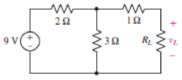
FIGURE 5.69
Expert Solution & Answer
Want to see the full answer?
Check out a sample textbook solution
Students have asked these similar questions
Combine the series voltage sources in Fig. 5.101 into a sin-
gle voltage source between points a and b.
YAN
4 V
+|||
-8V+
+6V-
Ob
a o
bo-
a o
bo
- 12 V +
- 10 V +
HO
+5V -
||||||
후
- 12 V +
+18 V-
- 12V +
- 8V+
6 V
-8V+
+||
6V
Hill
+8V-
4 V
t
<-8V+
VAINO
Hilt
+4V-
ob
Apply Mesh Analysis and Node Voltage Methods to Example 5.2-3) i.e., solve for i in
terms of R.
12 V
1+
4 ΚΩ
M
2 mA
R
5- Comment on the results obtained in the practically implemented and the
simulated circuits.
3 V3
V4
2 V2
4
Vs
6.
V6
10
Chapter 5 Solutions
Loose Leaf for Engineering Circuit Analysis Format: Loose-leaf
Ch. 5.1 - For the circuit of Fig. 5.4, use superposition to...Ch. 5.2 - For the circuit of Fig. 5.7, use superposition to...Ch. 5.2 - For the circuit of Fig. 5.18, compute the current...Ch. 5.2 - For the circuit of Fig. 5.20, compute the voltage...Ch. 5.3 - Using repeated source transformations, determine...Ch. 5.3 - Use Thvenins theorem to find the current through...Ch. 5.3 - Determine the Thvenin and Norton equivalents of...Ch. 5.3 - Find the Thvenin equivalent for the network of...Ch. 5.3 - Find the Thvenin equivalent for the network of...Ch. 5.4 - Consider the circuit of Fig. 5.43. FIGURE 5.43...
Ch. 5.5 - Prob. 11PCh. 5 - Linear systems are so easy to work with that...Ch. 5 - Prob. 2ECh. 5 - Prob. 3ECh. 5 - (a) Employ superposition to determine the current...Ch. 5 - (a) Using superposition to consider each source...Ch. 5 - (a) Determine the individual contributions of each...Ch. 5 - (a) Determine the individual contributions of each...Ch. 5 - After studying the circuit of Fig. 5.53, change...Ch. 5 - Consider the three circuits shown in Fig. 5.54....Ch. 5 - (a) Using superposition, determine the voltage...Ch. 5 - Employ superposition principles to obtain a value...Ch. 5 - (a) Employ superposition to determine the...Ch. 5 - Perform an appropriate source transformation on...Ch. 5 - (a) For the circuit of Fig. 5.59, plot iL versus...Ch. 5 - Determine the current labeled I in the circuit of...Ch. 5 - Verify that the power absorbed by the 7 resistor...Ch. 5 - (a) Determine the current labeled i in the circuit...Ch. 5 - (a) Using repeated source transformations, reduce...Ch. 5 - Prob. 19ECh. 5 - (a) Making use of repeated source transformations,...Ch. 5 - Prob. 21ECh. 5 - (a) With the assistance of source transformations,...Ch. 5 - For the circuit in Fig. 5.67 transform all...Ch. 5 - Prob. 24ECh. 5 - (a) Referring to Fig. 5.69, determine the Thevenin...Ch. 5 - (a) With respect to the circuit depicted in Fig....Ch. 5 - (a) Obtain the Norton equivalent of the network...Ch. 5 - (a) Determine the Thevenin equivalent of the...Ch. 5 - Referring to the circuit of Fig. 5.71: (a)...Ch. 5 - Prob. 30ECh. 5 - (a) Employ Thvenins theorem to obtain a...Ch. 5 - Prob. 32ECh. 5 - Determine the Norton equivalent of the circuit...Ch. 5 - For the circuit of Fig. 5.75: (a) Employ Nortons...Ch. 5 - (a) Obtain a value for the Thvenin equivalent...Ch. 5 - Prob. 36ECh. 5 - Obtain a value for the Thvenin equivalent...Ch. 5 - With regard to the network depicted in Fig. 5.79,...Ch. 5 - Determine the Thvenin and Norton equivalents of...Ch. 5 - Determine the Norton equivalent of the circuit...Ch. 5 - Prob. 41ECh. 5 - Determine the Thvenin and Norton equivalents of...Ch. 5 - Prob. 43ECh. 5 - Prob. 44ECh. 5 - Prob. 45ECh. 5 - (a) For the simple circuit of Fig. 5.87, find the...Ch. 5 - For the circuit drawn in Fig. 5.88, (a) determine...Ch. 5 - Study the circuit of Fig. 5.89. (a) Determine the...Ch. 5 - Prob. 49ECh. 5 - Prob. 50ECh. 5 - With reference to the circuit of Fig. 5.91, (a)...Ch. 5 - Prob. 52ECh. 5 - Select a value for RL in Fig. 5.93 such that it...Ch. 5 - Determine what value of resistance would absorb...Ch. 5 - Derive the equations required to convert from a...Ch. 5 - Convert the - (or "-") connected networks in Fig....Ch. 5 - Convert the Y-(or T-) connected networks in Fig....Ch. 5 - For the network of Fig. 5.97, select a value of R...Ch. 5 - For the network of Fig. 5.98, select a value of R...Ch. 5 - Prob. 60ECh. 5 - Calculate Rin as indicated in Fig.5.100. FIGURE...Ch. 5 - Employ Y conversion techniques as appropriate to...Ch. 5 - Prob. 63ECh. 5 - (a) Use appropriate techniques to obtain both the...Ch. 5 - (a) For the network in Fig. 5.104, replace the...Ch. 5 - Prob. 66ECh. 5 - Prob. 67ECh. 5 - A 2.57 load is connected between terminals a and...Ch. 5 - A load resistor is connected across the open...Ch. 5 - A backup is required for the circuit depicted in...Ch. 5 - (a) Explain in general terms how source...Ch. 5 - The load resistor in Fig. 5.108 can safely...Ch. 5 - Prob. 74ECh. 5 - As part of a security system, a very thin 100 ...Ch. 5 - With respect to the circuit in Fig. 5.90, (a)...
Knowledge Booster


Learn more about
Need a deep-dive on the concept behind this application? Look no further. Learn more about this topic, electrical-engineering and related others by exploring similar questions and additional content below.Similar questions
- Problem 5.5 Find (a) the Thevenin resistance R; directed from node a to node b. 7 Ohm 9 Ohm oa 4 A 8 Ohm 5 A ob (a) Rt = Ωarrow_forward5.40 Find the Norton equivalent of the circuit of Fig. 5-43. Reference I, up. Ans. 8 Ω.8Α 40 0 80 V 30 A 10 0 1000 V Fig. 5-43arrow_forward5.39 For the circuit shown in Fig. 5-42, find the Norton equivalent with , referenced positive toward terminal u. Ans. 4 , - 3 A 60 V 두 ח2ו Fig. 5-42arrow_forward
- * Q5: For the circuit shown, find R and Vs B C RΩ 2Ω. 3Ω ¥1 A 1 A F Vs A 1Ω D www www www wwwarrow_forwardSummary: Thevenin Equivalent Circult For the circuit in Figure 5: (a) Find the Open Circuit Voltage, voc, between terminals a and b by voltage division (do NOT use other methods) (b) Use the Deactivation Method to find the Thevenin Equlvalent Resistance between terminals a and b (c) Draw the Thevenin Equivalent Circuit with respect to terminals a and b. Figure 5 10 2 12 2 a 15 V 15 Ω 9.arrow_forwardThe circuit in the figure below is linear. When Is = 0.3 A and Vs = 10 V, lo = 0.6 A; and when Is 0.9 A and Vs = 15 V, lo = 1.05 A Then by superposition, when Is = 0.75 A and Vs = 20 V, lo equals: R3 R4 a.0.6 A 1. 1.25 A إزالة العلامة المائية CamScanner - Ligb äs In the cirruit shown, the ammeter readh 40 mA and the voltmeter reads 16 V. Calcudate the internal resistances of the ammeter (Ra) a the voltneter (Ru 90 2 20 V 500 n3 BR50 & R2MO CR10& R, 2 MOarrow_forward
- a. Design the circuit in Fig. 5.117 such that VR₂ = 3VR, and VR₂ 4 VR₂ b. If the current is reduced to 10 μA, what are the new val- ues of R₁, R₂, and R3? How do they compare to the re- sults of part (a)? AL- = إسكان E 10 mA 4₁₁ www www R₁ R₂ 64 V R3 wwwarrow_forwardConsider the following circuit. 5.9 Ω www 42 V 17.0 Ω www 4.3 Ω www 3.0 Ω ww 1.3 Ω 17.0 Ω Find the equivalent resistance. Answer in units of Ω. 3.0 Ω www 3.0 Ω w 4.3 Ωarrow_forwardQ5: For the circuit shown, find Rab 5Ω 10Ω d wwo a bow e 20 Ω 3 2arrow_forward
- 4. A) Reduce the given circuit to the fewest possible components thru series/parallel combinations B) Determine Vx if all resistors are 10k, all capacitors are 50 uF and all inductors are 1mH R ww HHH R R 9 V EE104 - BASIC ELECTRICAL ENGINEERING R Rarrow_forwardLet R = : 2 ΚΩ in the circuit of Fig. 5_5. What is Rin? R R 2 ΚΩ 3 ΚΩ 24 ΚΩ 3.27 ΚΩ Fig. 5_5 R Riaarrow_forwardQuestion 27 a) Obtain the Norton equivalent of the network connected to R₂ in Fig. 5.70. Obtain the Thévenin equivalent of the same network. b) c) Use either to calculate i, for R₂ = 0 2,1 2, 4.923 , and 8.107 2. 1 A FIGURE 5.70 5Ω 5Ω 0.8 Ω 202 RLarrow_forward
arrow_back_ios
SEE MORE QUESTIONS
arrow_forward_ios
Recommended textbooks for you
 Introductory Circuit Analysis (13th Edition)Electrical EngineeringISBN:9780133923605Author:Robert L. BoylestadPublisher:PEARSON
 Delmar's Standard Textbook Of ElectricityElectrical EngineeringISBN:9781337900348Author:Stephen L. HermanPublisher:Cengage Learning
 Programmable Logic ControllersElectrical EngineeringISBN:9780073373843Author:Frank D. PetruzellaPublisher:McGraw-Hill Education
 Fundamentals of Electric CircuitsElectrical EngineeringISBN:9780078028229Author:Charles K Alexander, Matthew SadikuPublisher:McGraw-Hill Education
 Electric Circuits. (11th Edition)Electrical EngineeringISBN:9780134746968Author:James W. Nilsson, Susan RiedelPublisher:PEARSON
 Engineering ElectromagneticsElectrical EngineeringISBN:9780078028151Author:Hayt, William H. (william Hart), Jr, BUCK, John A.Publisher:Mcgraw-hill Education,
Introductory Circuit Analysis (13th Edition)
Electrical Engineering
ISBN:9780133923605
Author:Robert L. Boylestad
Publisher:PEARSON
Delmar's Standard Textbook Of Electricity
Electrical Engineering
ISBN:9781337900348
Author:Stephen L. Herman
Publisher:Cengage Learning
Programmable Logic Controllers
Electrical Engineering
ISBN:9780073373843
Author:Frank D. Petruzella
Publisher:McGraw-Hill Education
Fundamentals of Electric Circuits
Electrical Engineering
ISBN:9780078028229
Author:Charles K Alexander, Matthew Sadiku
Publisher:McGraw-Hill Education
Electric Circuits. (11th Edition)
Electrical Engineering
ISBN:9780134746968
Author:James W. Nilsson, Susan Riedel
Publisher:PEARSON
Engineering Electromagnetics
Electrical Engineering
ISBN:9780078028151
Author:Hayt, William H. (william Hart), Jr, BUCK, John A.
Publisher:Mcgraw-hill Education,
Z Parameters - Impedance Parameters; Author: Electrical Engineering Authority;https://www.youtube.com/watch?v=qoD4AoNmySA;License: Standard Youtube License