
Loose Leaf for Engineering Circuit Analysis Format: Loose-leaf
9th Edition
ISBN: 9781259989452
Author: Hayt
Publisher: Mcgraw Hill Publishers
expand_more
expand_more
format_list_bulleted
Concept explainers
Videos
Textbook Question
Chapter 5, Problem 15E
Determine the current labeled I in the circuit of Fig. 5.60 by first performing source transformations and parallel–series combinations as required to reduce the circuit to only three elements.
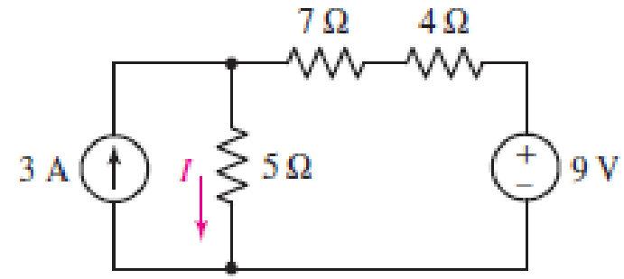
■ FIGURE 5.60
Expert Solution & Answer

Trending nowThis is a popular solution!

Students have asked these similar questions
Explain in detail the difference between a Micro-Electronics / Photonics Engineer and an Electronic Circuit Design Engineer. Be specific and provide details. Please cite all your sources.
• Could these engineers have projects in common? Give examples answer all two
R1
For the above circuit, use the RTh short circuit method to determine the short circuit current, Isc, in
Amps across the (a,b) terminals. Round your answer to the nearest single digit decimal place and do
not enter units.
Given that
I = 11A
R1 =72
R2 =52
R, =60
RL =52
Determine Isc in Amps
Determine the Equivalent Resistance (Rab) of the circuit. ( please provide illustrations/drawings it is needed for our solutions)
Chapter 5 Solutions
Loose Leaf for Engineering Circuit Analysis Format: Loose-leaf
Ch. 5.1 - For the circuit of Fig. 5.4, use superposition to...Ch. 5.2 - For the circuit of Fig. 5.7, use superposition to...Ch. 5.2 - For the circuit of Fig. 5.18, compute the current...Ch. 5.2 - For the circuit of Fig. 5.20, compute the voltage...Ch. 5.3 - Using repeated source transformations, determine...Ch. 5.3 - Use Thvenins theorem to find the current through...Ch. 5.3 - Determine the Thvenin and Norton equivalents of...Ch. 5.3 - Find the Thvenin equivalent for the network of...Ch. 5.3 - Find the Thvenin equivalent for the network of...Ch. 5.4 - Consider the circuit of Fig. 5.43. FIGURE 5.43...
Ch. 5.5 - Prob. 11PCh. 5 - Linear systems are so easy to work with that...Ch. 5 - Prob. 2ECh. 5 - Prob. 3ECh. 5 - (a) Employ superposition to determine the current...Ch. 5 - (a) Using superposition to consider each source...Ch. 5 - (a) Determine the individual contributions of each...Ch. 5 - (a) Determine the individual contributions of each...Ch. 5 - After studying the circuit of Fig. 5.53, change...Ch. 5 - Consider the three circuits shown in Fig. 5.54....Ch. 5 - (a) Using superposition, determine the voltage...Ch. 5 - Employ superposition principles to obtain a value...Ch. 5 - (a) Employ superposition to determine the...Ch. 5 - Perform an appropriate source transformation on...Ch. 5 - (a) For the circuit of Fig. 5.59, plot iL versus...Ch. 5 - Determine the current labeled I in the circuit of...Ch. 5 - Verify that the power absorbed by the 7 resistor...Ch. 5 - (a) Determine the current labeled i in the circuit...Ch. 5 - (a) Using repeated source transformations, reduce...Ch. 5 - Prob. 19ECh. 5 - (a) Making use of repeated source transformations,...Ch. 5 - Prob. 21ECh. 5 - (a) With the assistance of source transformations,...Ch. 5 - For the circuit in Fig. 5.67 transform all...Ch. 5 - Prob. 24ECh. 5 - (a) Referring to Fig. 5.69, determine the Thevenin...Ch. 5 - (a) With respect to the circuit depicted in Fig....Ch. 5 - (a) Obtain the Norton equivalent of the network...Ch. 5 - (a) Determine the Thevenin equivalent of the...Ch. 5 - Referring to the circuit of Fig. 5.71: (a)...Ch. 5 - Prob. 30ECh. 5 - (a) Employ Thvenins theorem to obtain a...Ch. 5 - Prob. 32ECh. 5 - Determine the Norton equivalent of the circuit...Ch. 5 - For the circuit of Fig. 5.75: (a) Employ Nortons...Ch. 5 - (a) Obtain a value for the Thvenin equivalent...Ch. 5 - Prob. 36ECh. 5 - Obtain a value for the Thvenin equivalent...Ch. 5 - With regard to the network depicted in Fig. 5.79,...Ch. 5 - Determine the Thvenin and Norton equivalents of...Ch. 5 - Determine the Norton equivalent of the circuit...Ch. 5 - Prob. 41ECh. 5 - Determine the Thvenin and Norton equivalents of...Ch. 5 - Prob. 43ECh. 5 - Prob. 44ECh. 5 - Prob. 45ECh. 5 - (a) For the simple circuit of Fig. 5.87, find the...Ch. 5 - For the circuit drawn in Fig. 5.88, (a) determine...Ch. 5 - Study the circuit of Fig. 5.89. (a) Determine the...Ch. 5 - Prob. 49ECh. 5 - Prob. 50ECh. 5 - With reference to the circuit of Fig. 5.91, (a)...Ch. 5 - Prob. 52ECh. 5 - Select a value for RL in Fig. 5.93 such that it...Ch. 5 - Determine what value of resistance would absorb...Ch. 5 - Derive the equations required to convert from a...Ch. 5 - Convert the - (or "-") connected networks in Fig....Ch. 5 - Convert the Y-(or T-) connected networks in Fig....Ch. 5 - For the network of Fig. 5.97, select a value of R...Ch. 5 - For the network of Fig. 5.98, select a value of R...Ch. 5 - Prob. 60ECh. 5 - Calculate Rin as indicated in Fig.5.100. FIGURE...Ch. 5 - Employ Y conversion techniques as appropriate to...Ch. 5 - Prob. 63ECh. 5 - (a) Use appropriate techniques to obtain both the...Ch. 5 - (a) For the network in Fig. 5.104, replace the...Ch. 5 - Prob. 66ECh. 5 - Prob. 67ECh. 5 - A 2.57 load is connected between terminals a and...Ch. 5 - A load resistor is connected across the open...Ch. 5 - A backup is required for the circuit depicted in...Ch. 5 - (a) Explain in general terms how source...Ch. 5 - The load resistor in Fig. 5.108 can safely...Ch. 5 - Prob. 74ECh. 5 - As part of a security system, a very thin 100 ...Ch. 5 - With respect to the circuit in Fig. 5.90, (a)...
Knowledge Booster


Learn more about
Need a deep-dive on the concept behind this application? Look no further. Learn more about this topic, electrical-engineering and related others by exploring similar questions and additional content below.Similar questions
- Hi! I just need an explanation regarding this question :) Compare the calculated and measured values (for different values of R) and determine whether they agree or are very close in value. Explain your findings.arrow_forwardThis is Circuits. Provide solutionarrow_forwardLMH_chapter3-part 1-homework [Protected View] PowerPoint ĐĂNG PHẠM HỒNG File Home Insert Design Transitions Animations Slide Show Review View Help Tell me what you want to do & Share 6. HW18 5.20 In the circuit of Fig. 5.59, calculate v, of v; = 0. HW20 8 ka 4 4 ka 5.32 Calculate iz and v, in the circuit of Fig. 5.70. Find the power dissipated by the 30-kN resistor. 7 HW19 3.24 In the circuit shown in Fig 5.62, find k in the voltage transfer flunction ,- , 48 k2 ww ww 8 4 mV 50 k2 HW20 60 k2 30 Ω 5.32 Calculate i, and e, in the circuit of Fig. 5.70. Find the power dissipated by the 30 kl resistor 10 kΩ 4 mv ( 50 ka 60 30 k2 10 k2 9. HW21 5.33 Re:kn lo the p m tineuit in Fip 571 Caknulale4 ud the pomer disupated by dhe kil resistor. 1 kI 8 3 ma O ww- wwarrow_forward
- show your complete solution. need asaparrow_forwardDigital lab & design The circuits don’t have to be created in proteus project just a normal drawing on paper will do, thanks. 3)arrow_forwardCan someone please help me out and provide the full solution and answer for this example, I need it as my reviewer. Thank you so much!arrow_forward
- State which of the following statements are true and which are false. Give reasons for youranswers.a) A very simple circuit consists of a battery connected across a resistor. In this circuit, thebattery and the resistor are both in series and also in parallel.b) A resistor R and a capacitor C connected in series combine as 1RC =1R +1Cc) Natural uranium is not radioactive until it has been processed by enrichment for use infission reactors or bombs.d) Infrared light is more likely to cause electrons to be emitted from a metal than ultravioletlight.e) Special and General Relativity effects both matter for the operation of GPS, the former slowing down the clocks on GPS satellites relative to clocks on Earth and the latter speedingthem up.arrow_forward(c) Solve the voltages (Vrms) across the two resistors and capacitor. Attach your neat and complete solution. Thanks!arrow_forwardUse the current divider rule to calculate the theoretical currents I, ID , and IE . (RECONSTRUCT THE CIRCUIT IN ITS EQUIVALENT WYE FORM)arrow_forward
- Given the circuit below. The current through the 100 resistor in the circuit below is 8.0 mA. Determine the 2002 5.0 (2 [www] 10:2 a) total resistance b) total current c) total voltage 30 2 www wwww 5.002 4002arrow_forwardhow long will it take to charge a 1000μF capacitor through 1 KQ resistor to full 16V source voltage? d) forever a) 1000 microseconds b) 10seconds c) one day d) forever What maximum voltage can be safely applied to series resistors, 1.2 KQ ¹4 W and 680 0%W? a) 9.81V b) 17.32. V c)27.07 V d) 32.52V When a capacitor is being charged from a 12V power source, the current flowing through thecapacitor will a} increase b} decrease c) remain the same d) can't be determined Calculate the voltmeter reading in the circuit shown in the figure when wiper arm of the potentiometer is set at 25% up fromthe bottom. note: the resistance value is 3.3 Kilo-ohms. 9V Oa) 2.13 V b) 3.12 V c)2.31 V d) 6.25 V 1k 3k3arrow_forwardhow long will it take to charge a 1000μF capacitor through 1 KQ resistor to full 16V source voltage? d) forever a) 1000 microseconds b) 10seconds c) one day d) forever What maximum voltage can be safely applied to series resistors, 1.2 KQ 14 W and 680 0%W? a) 9.81V b) 17.32. V c)27.07 V d) 32.52V When a capacitor is being charged from a 12V power source, the current flowing through thecapacitor will a} increase b} decrease c) remain the same d) can't be determined Calculate the voltmeter reading in the circuit shown in the figure when wiper arm of the potentiometer is set at 25% up fromthe bottom. note: the resistance value is 3.3 Kilo-ohms. 9V a) 2.13 V b) 3.12 V c)2.31 V d) 6.25 V 1k 3k3arrow_forward
arrow_back_ios
SEE MORE QUESTIONS
arrow_forward_ios
Recommended textbooks for you
 Introductory Circuit Analysis (13th Edition)Electrical EngineeringISBN:9780133923605Author:Robert L. BoylestadPublisher:PEARSON
 Delmar's Standard Textbook Of ElectricityElectrical EngineeringISBN:9781337900348Author:Stephen L. HermanPublisher:Cengage Learning
 Programmable Logic ControllersElectrical EngineeringISBN:9780073373843Author:Frank D. PetruzellaPublisher:McGraw-Hill Education
 Fundamentals of Electric CircuitsElectrical EngineeringISBN:9780078028229Author:Charles K Alexander, Matthew SadikuPublisher:McGraw-Hill Education
 Electric Circuits. (11th Edition)Electrical EngineeringISBN:9780134746968Author:James W. Nilsson, Susan RiedelPublisher:PEARSON
 Engineering ElectromagneticsElectrical EngineeringISBN:9780078028151Author:Hayt, William H. (william Hart), Jr, BUCK, John A.Publisher:Mcgraw-hill Education,
Introductory Circuit Analysis (13th Edition)
Electrical Engineering
ISBN:9780133923605
Author:Robert L. Boylestad
Publisher:PEARSON
Delmar's Standard Textbook Of Electricity
Electrical Engineering
ISBN:9781337900348
Author:Stephen L. Herman
Publisher:Cengage Learning
Programmable Logic Controllers
Electrical Engineering
ISBN:9780073373843
Author:Frank D. Petruzella
Publisher:McGraw-Hill Education
Fundamentals of Electric Circuits
Electrical Engineering
ISBN:9780078028229
Author:Charles K Alexander, Matthew Sadiku
Publisher:McGraw-Hill Education
Electric Circuits. (11th Edition)
Electrical Engineering
ISBN:9780134746968
Author:James W. Nilsson, Susan Riedel
Publisher:PEARSON
Engineering Electromagnetics
Electrical Engineering
ISBN:9780078028151
Author:Hayt, William H. (william Hart), Jr, BUCK, John A.
Publisher:Mcgraw-hill Education,
Latches and Flip-Flops 1 - The SR Latch; Author: Computer Science;https://www.youtube.com/watch?v=-aQH0ybMd3U;License: Standard Youtube License