
Videos
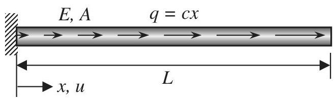
Consider the uniform bar in the figure. Axial load q is linearly distributed along the length of the bar according to
Want to see the full answer?
Check out a sample textbook solution
Chapter 2 Solutions
Introduction To Finite Element Analysis And Design
Additional Engineering Textbook Solutions
Engineering Mechanics: Dynamics (14th Edition)
Fox and McDonald's Introduction to Fluid Mechanics
Thinking Like an Engineer: An Active Learning Approach (3rd Edition)
Applied Fluid Mechanics (7th Edition)
Engineering Mechanics: Statics
Introduction to Heat Transfer


- A wine of length L = 4 ft and diameter d = 0.125 in. is stretched by tensile forces P = 600 lb. The wire is made of a copper alloy having a stress-strain relationship that may be described mathematically by =18,0001+30000.03(=ksi) in which is nondimensional and has units of kips per square inch (ksi). (a) Construct a stress-strain diagram for the material. (bj Determine the elongation, of the wire due to the Forces P. (c) IF the forces are removed, what is the permanent set of the bar? (d) If the forces are applied again, what is the proportional limit?arrow_forwardSolve the preceding problem if the cross- sectional dimensions are b = 1.5 in. and h = 5.0 in., the gage angle is ß = 750, the measured strains are = 209 × 10-6 and B = -110 × 10, and the material is a magnesium alloy with modulus E = 6.0 X 10⁶ psi and Poisson’s ratio v = 0.35.arrow_forwardA round bar ABC of length 2L (see figure) rotates about an axis through the midpoint C with constant angular speed w (radians per second). The material of the bar has weight density y. (a) Derive a formula for the tensile stress a’ in the bar as a function of the distance x from the midpoint C. (b) What is the maximum tensile stress a max?arrow_forward
- Solve the preceding problem for the following data:P = 160 kN,JV = 200 tN,L = 2 m,b = 95 mm, h = 300 mm, and d = 200 mmarrow_forwardSolve the preceding problem for the following data: b = 8.0 in., k = 16 lb/in., a = 45°, and P = 10 lb.arrow_forwardAn aluminum bar subjected to tensile Forces P has a length L = 150 in. and cross-sectional area A = 2.0 in2 The stress-strain behavior of the aluminum may be represented approximately by the bilinear stress-strain diagram shown in the figure. Calculate the elongation S of the bar for each of the following axial loads: p = 8 kips, 16 kips. 24 kips, 32 kips, and 40 kips. From these results, plot a diagram of load P versus elongation S (load-displacement diagram).arrow_forward
- An clement of material in plane strain (see figure) is subjected to strains ex= 480 × 10-6, Ey= 70 × l0-6, and yxy= 420 × l0-6. Determine the following quantities: (a) the strains for an element oriented at an angle 0 = 75°, (b) the principal strains, and (c) the maximum shear strains. Show the results on sketches of properly oriented elements.arrow_forwardA prismatic bar in tension has a length L = 2.0 m and cross-sectional area A =249 mn2. The material of the bar has the stress-strain curve shown in the figure. Determi ne t he elongation 5 of the bar for each of the following axial loads: P = 10 kN, 20 kN, 30 kN, 40 kN. and 45 kN. From these results, plot a diagram of load P versus elongation 5 (load-displacement diagram).arrow_forwardA circular aluminum tube of length L = 600 mm is loaded in compression by forces P (see figure). The outside and inside diameters are d2= 75 mm and d1= 63 mm, respectively. A strain gage is placed on the outside of the lube to measure normal strains in the longitudinal direction. Assume that E = 73 GPa and Poissons ratio is v = 0.33. (a) IF the compressive stress in the tube is 57 MPa, what is the load P? (b) If the measured strain is e = 78 J X 10-6, what is the shorteningarrow_forward
- -11 A solid steel bar (G = 11.8 X 10⁶ psi ) of diameter d = 2,0 in. is subjected to torques T = 8.0 kip-in. acting in the directions shown in the figure. Determine the maximum shear, tensile, and compressive stresses in the bar and show these stresses on sketches of properly oriented stress elements. Determine the corresponding maximum strains (shear, tensile, and compressive) in the bar and show these strains on sketches of the deformed elements.arrow_forwardA bar with a circular cross section having two different diameters d and 2d is shown in the figure. The length of each segment of the bar is L/2T and the modulus of elasticity of the material is E. (a) Obtain a formula for the strain energy U of the bar due to the load P. (b) Calculate the strain energy if the load P = 27 kN, the length L = 600 mm, the diameter d = 40 mm, and the material is brass with E = 105 GPa.arrow_forwardA uniformly tapered lube AB of circular cross section and length L is shown in the figure. The average diameters at the ends are dAand d£= 2d t. Assume E is constant. Find the elongation S of the tube when it is subjected to loads P acting at the ends. Use the following numerical data:^ = 35 mm, L = WO mm, E = 2.1 GPa. and P = 25 tN. Consider the following cases. (a) A hole of constant diameter dAis drilled from B toward A to form a hollow section of length x - U2. (b) A hole of variable diameter a\.x) is drilled, from B toward A to form a hollow section of length x = L/2 and constant thickness t = dA/20.arrow_forward
 Mechanics of Materials (MindTap Course List)Mechanical EngineeringISBN:9781337093347Author:Barry J. Goodno, James M. GerePublisher:Cengage Learning