
Videos
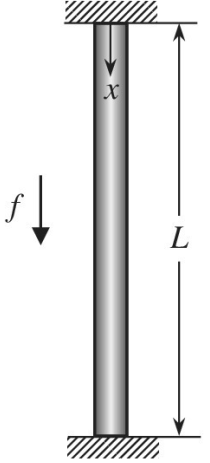
A vertical rod of elastic material is fixed at both ends with constant cross-sectional area A, Young’s modulus E, and height of L under the distributed load f per unit length. The vertical deflection
Using three elements of equal length, solve for
Want to see the full answer?
Check out a sample textbook solution
Chapter 2 Solutions
Introduction To Finite Element Analysis And Design
Additional Engineering Textbook Solutions
Statics and Mechanics of Materials (5th Edition)
Degarmo's Materials And Processes In Manufacturing
Applied Statics and Strength of Materials (6th Edition)
Engineering Mechanics: Statics
INTERNATIONAL EDITION---Engineering Mechanics: Statics, 14th edition (SI unit)
Heating Ventilating and Air Conditioning: Analysis and Design


- A 1D two-node bar element as shown below is considered. The displacement of node 1 is q₁=0.002 mm, and the displacement of point pis qp=0.013 mm. Using 1D linear shape functions, determine the displacement of node 2 (92) in mm? Hint: round off your final answer to 5 decimal places; e.g. if your answer is 1.2345678, then rounding-off to 5 decimal places yields 1.23457 and that is the value which you need to type in the answer box. 1 Parrow_forwardAnalyse the statically determinate bar illustrated below by expressing the loading as a single function using Macaulay brackets and the Dirac delta, integrating to find th axial force and integrating again to find the displacements, applying the boundary conditions appropriately. Find the axial force in the bar at point A and the displaceme at point B. The cross section of the bar is constant with EA = 18000 kN. a = 4 m, b = 2 m, c = 2 m and d = 4 m. w1 = 12 kN/m, w2 = 17 kN/m,, P1 = 12 kN and P2 = 19kN. a W1 L/2 W2 Multiple Choice Answers Multiple Choice Answer: Axial force at point A (kN, tension positive): a. 3.31 b. 31.97 c. 37.33 d. 31 Multiple Choice Answer: Displacement at point B (mm, positive to right): a. 0.0061 b. 0.0395 c. 0.0193 d. 0.0261 Axial force at point A (kN, tension positive): Displacement at point B (mm, positive to right): L/2 P1 P2 (type in your multiple choice answer, e.g. a, b, c or d) (type in your multiple choice answer, e.g. a, b, c or d)arrow_forwardA 50-mm diameter cylinder is made of a brass for which the stress-strain diagram is as shown. The angle of twist is 5° in a length L = 725 mm. The three points on the nonlinear stress-strain diagram used are (0, 0), (0.0015, 55 MPa), and (0.003, 80 MPa). By fitting the polynomial T = A + By + Cy² through these points, the following approximate relation has been obtained. T= 46.7 × 10%y-6.67 × 10¹²/2 Determine the magnitude Tof torque applied to the shaft using this relation and the two equations given below. Y Ty - ρφ T (MPa) 2π ζ ρ?τὰρ 100 80 60 40 20 0 0.001 0.002 0.003 Y d = 50 mm L The magnitude T of torque applied to the shaft is kN.m.arrow_forward
- Question 4 Consider a thin rectangular cantilever beam of linear elastic and isotropic material in Figure 2. The solution to this two dimensional plane stress problem under point load, F and moment, M is obtained from the Airy's stress function as: i. ii. Φ y M 40313. F Figure 2 ——▬▬▬▬▬▬▬▬▬▬ y² Determine the stress components. Using boundary conditions, investigate how the load F and M are applied to the beam to satisfy the given Airy function. 4c X OL 2c t=1arrow_forwardQuestion 2 Determine the factor of safety against slope failure by means of the stability number method for the slope shown in the figure below. 25 ft Homogeneous Soil e 500 Ibn 35 Y- 125 Ibnarrow_forwardA 50-mm diameter cylinder is made of a brass for which the stress-strain diagram is as shown. The angle of twist is 5° in a length L = 845 mm. The three points on the nonlinear stress-strain diagram used are (0, 0), (0.0015, 55 MPa), and (0.003, 80 MPa). By fitting the polynomial T = A + By+ Cy2 through these points, the following approximate relation has been obtained. T= 46.7 x 10y-6.67 × 10122 Determine the magnitude T of torque applied to the shaft using this relation and the two equations given below. P4 Y = Ty = 2π] ρ?τὰρ 7 (MPa) 100 80 60 40 20 0 0,001 0.002 0.003 Y d = 50 mm "K The magnitude T of torque applied to the shaft is KN-m. A²arrow_forward
- A long circular shaft of length L with variable cross-section is fixed onto rigid walls as shown in Figure 1.1. The polar moment of inertia of the L/3-long segment (J1) with a larger cross section is three times larger than that of a 2L/3-long segment (J2) on the right. Assume the shear modulu is constant and equal to G for the entire shaft and that strains are small and linear elastic. L/3 a b L/3 L/3 Figure 1.1. Shaft with variable cross-section and external torque T. (a) If the shaft is subjected to an external torque T at point b, find the angle of twist of point b with respect to point a. (b) If the shaft is subjected to an external torque T at point a, as shown in Figure 1.2, find the angle of twist of point a with respect to point b. J2 L/3- L/3 L/3arrow_forwardA transmission tower (a truss) for supporting electric wires is shown. The load of wire at D is shown as force F1 at an angle of a and the load of wire at A is shown as force F2 at an angle of B. Using the values given in the table below: F1 (N) F: (N) a (deg) B (deg) w (m) h (m) Value 150 70 30 60 2 a) Find the reaction forces at supports Y and Z. b) Determine the forces supported by members DO, DM, SV, and UX and specify whether the member is in Tension or Compression. M Q B F1 F2 T W X harrow_forwardDont Copy from chegg need step wise step and correct answers only Use Finite Elemental method Assemble element stiffness matrix for the member of plane frame shown in Figure is oriented at angle 30° to the x-axis. Take E= 200 GPa, I=4 × 10⁶ m* and A = 4 × 10-³m². ,if it 5m 30arrow_forward
- Given that the cross-sectional area for all members is 1000 mm² and modulus of elasticity is 200 GPa 2m B Determine: -500 N 45° -2m- (a) C A. The member stiffness matrix for each member B. The transformation matrix for each memberarrow_forwardshboard Events My Courses This course EHide blocks Question 6 The following figure represents a bar problem in static equilibrium and the related linear finite element model (The bar is modeled by one linear element). The bar is made of steel with modulus of elasticity E = 200 GPa and it has a length of 1 m and a cross-sectional area A = 10 cm?. If the bar is fixed at one end and subjected to a uniform distributed load of intensity w = 1 kN/m and a concentrated force F = 5 kN at its free end as shown, what would be the displacement at global node 2? Not yet answered Marked out of 15.00 P Flag question 1 kN/m F-5 KN L=1m 2 1229 AM O a d ENG 4/30/2021 re to search 近arrow_forwardConsider a slender body fixed at the root (x = 0). The cross-sectional area along the span is A = Ao(1 – 0.5x/L), where Ao and L are given. The slender body is modeled using three elements of equal length. Construct the stiffness matrix of element #2.arrow_forward
 Elements Of ElectromagneticsMechanical EngineeringISBN:9780190698614Author:Sadiku, Matthew N. O.Publisher:Oxford University Press
 Mechanics of Materials (10th Edition)Mechanical EngineeringISBN:9780134319650Author:Russell C. HibbelerPublisher:PEARSON
 Thermodynamics: An Engineering ApproachMechanical EngineeringISBN:9781259822674Author:Yunus A. Cengel Dr., Michael A. BolesPublisher:McGraw-Hill Education
 Control Systems EngineeringMechanical EngineeringISBN:9781118170519Author:Norman S. NisePublisher:WILEY
 Mechanics of Materials (MindTap Course List)Mechanical EngineeringISBN:9781337093347Author:Barry J. Goodno, James M. GerePublisher:Cengage Learning
 Engineering Mechanics: StaticsMechanical EngineeringISBN:9781118807330Author:James L. Meriam, L. G. Kraige, J. N. BoltonPublisher:WILEY