
Loose Leaf for Engineering Circuit Analysis Format: Loose-leaf
9th Edition
ISBN: 9781259989452
Author: Hayt
Publisher: Mcgraw Hill Publishers
expand_more
expand_more
format_list_bulleted
Concept explainers
Videos
Textbook Question
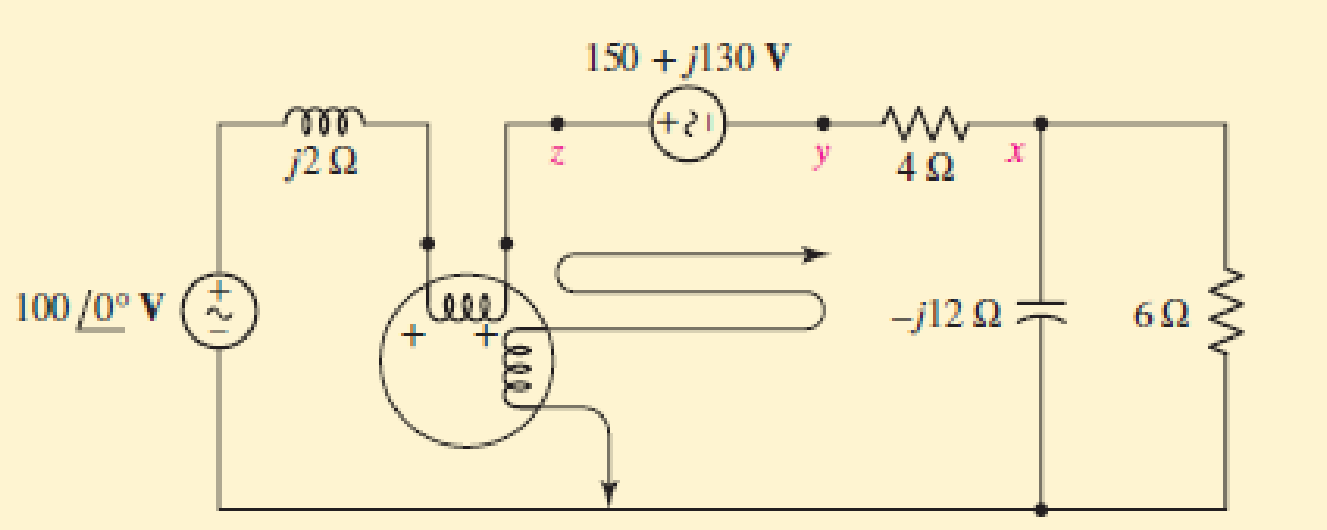
Chapter 12.5, Problem 9P
Determine the wattmeter reading in Fig. 12.24, state whether or not the potential coil had to be reversed in order to obtain an upscale reading, and identify the device or devices absorbing or generating this power. The (+) terminal of the wattmeter is connected to (a) x; (b) y; (c) z.
Expert Solution & Answer
Want to see the full answer?
Check out a sample textbook solution
Students have asked these similar questions
Q4: A 50 Hz, 11KV, 3-ph, alternator with earthed neutral has a reactance of 5 Ω\ ph and is connected to bus bar through a C.B. The distributed capacitance up to C.B between phase and neutral is 0.01μF, determine: 1-the recovery voltage across the contacts of the breaker, 2-the frequency of oscillation, 3- The restriking voltage across the contacts of the breaker, 4-the average rate of rise of restriking voltage up to the first peak, 5- the time to reach the peak restriking voltage, 6- the value of resistance to be used across the contacts of C.B. to eliminate the restriking voltage, and 7- the value of inductance and capacitance of this system
Q1: A 50HZ,11KV,3-ph,alternator with earthed neutral
has a reactance of 50\ph and is connected to bus bar
through a C.B.The distributed capacitance up to C.B
between phase and neutral is 0.01HF,Determine:
1-The restriking voltage across the contacts of the
breaker,
2-The frequency of oscillation,and
3-The voltage across the capacitance.
(if the
disconnecting capacitive tank)?
Q2:Repeat (1,2,and 3) in Q1 if the P.F. of the fault was
capacitance
current
breaking
due
to
0.4?
Q3:Repeat (1,2,and 3) in Q1 if the current chops at an
instantaneous rate of 8A?
4. A 3-phase, 50 Hz, star -connected, 2000 kVA, 2300 V alternator gives a short-circuit current of 600 A for a certain field excitation. With the same excitation, the open-circuit voltage was 900 V. The resistance between a pair of terminals was 0.12 ohm. Find full-load regulation at(i) Unity pf(ii) 0.8 pf lagging(iii) 0.8 pf leading
Chapter 12 Solutions
Loose Leaf for Engineering Circuit Analysis Format: Loose-leaf
Ch. 12.1 - Let and . Find (a) Vad; (b) Vbc; (c) Vcd.Ch. 12.2 - Prob. 2PCh. 12.2 - Modify Fig. 12.9 by adding a 1.5 resistance to...Ch. 12.3 - A balanced three-phase three-wire system has a...Ch. 12.3 - A balanced three-phase three-wire system has a...Ch. 12.3 - Three balanced Y-connected loads are installed on...Ch. 12.4 - Each phase of a balanced three-phase -connected...Ch. 12.4 - Prob. 8PCh. 12.5 - Determine the wattmeter reading in Fig. 12.24,...Ch. 12.5 - Prob. 10P
Ch. 12 - Prob. 1ECh. 12 - Prob. 2ECh. 12 - Prob. 3ECh. 12 - Describe what is meant by a polyphase source,...Ch. 12 - Prob. 5ECh. 12 - Prob. 6ECh. 12 - Prob. 7ECh. 12 - Prob. 8ECh. 12 - Prob. 9ECh. 12 - Prob. 10ECh. 12 - The single-phase three-wire system of Fig. 12.31...Ch. 12 - Prob. 12ECh. 12 - Referring to the balanced load represented in Fig....Ch. 12 - Prob. 14ECh. 12 - Prob. 15ECh. 12 - Consider a simple positive phase sequence,...Ch. 12 - Assume the system shown in Fig. 12.34 is balanced,...Ch. 12 - Repeat Exercise 17 with Rw = 10 , and verify your...Ch. 12 - Prob. 19ECh. 12 - Prob. 20ECh. 12 - Prob. 21ECh. 12 - Prob. 22ECh. 12 - A three-phase system is constructed from a...Ch. 12 - Prob. 24ECh. 12 - Each load in the circuit of Fig. 12.34 is composed...Ch. 12 - Prob. 26ECh. 12 - Prob. 27ECh. 12 - A three-phase load is to be powered by a...Ch. 12 - For the two situations described in Exercise 28,...Ch. 12 - Prob. 30ECh. 12 - Prob. 31ECh. 12 - Prob. 32ECh. 12 - Repeat Exercise 32 if Rw = 1 . Verify your...Ch. 12 - Prob. 34ECh. 12 - Prob. 35ECh. 12 - Prob. 36ECh. 12 - A wattmeter is connected into the circuit of Fig....Ch. 12 - Find the reading of the wattmeter connected in the...Ch. 12 - (a) Find both wattmeter readings in Fig. 12.39 if...Ch. 12 - Circuit values for Fig. 12.40 are , , , , . Find...Ch. 12 - Prob. 41ECh. 12 - Prob. 42ECh. 12 - (a) Is the load represented in Fig. 12.41...Ch. 12 - Prob. 44E
Knowledge Booster


Learn more about
Need a deep-dive on the concept behind this application? Look no further. Learn more about this topic, electrical-engineering and related others by exploring similar questions and additional content below.Similar questions
- a) Find the ICA load current b) Give the voltage Vab c) Calculate the total complex power on voltage sources.arrow_forwardQ1) A power is to be distributed to the consumers either by a 3-wire DC system or by a 3- phase three wire system .Compare the amount of copper required in the two systems .Assume the same voltage between the outer wire and neutral wire . same percentage loss, balanced load and unity power factor . the middle wires are of half of cross-sectional area as that of outersarrow_forward56. A single phase thyristor adjust line spacing converter with a resistive load is shown below: V₂ = V sinest SCR ER R V₂ (B) 1.11 (D) 1.44 If the supply voltage is 230V (rms) at 50 Hz, calculate ripple factor for firing angle a-45" and R - 100 9. (A) I (C) 1.21arrow_forward
- 2.A coil takes 30 A at 0.84 lagging power factor when connected to a 250 V, 60 Hz supply. Determine the value of a single element to be connected and power taken by the circuit which when connected in parallel with the circuit will reduce the line current to a minimumarrow_forward12.31. How would you realise a terminal voltage of 10 V using solar cells of the type characterised in Fig. 12.20?arrow_forward56. A single phase thyristor adjust line spacing converter with a resistive load is shown below: V₂ = V₂ sinet SCR ER V₂ If the supply voltage is 230V (rms) at 50 Hz, calculate ripple factor for firing angle a -45° and R = 100 Q. (A) I (C) 1.21 (B) 1.11 (D) 1.44arrow_forward
- Tutorial Qut stion. Tutorial Solution. Unit 2- Power Tra... EE321 Course No. Subscribe Tutorial Questions - Power Transformers.pdf 13. The figure below shows part of a power system consisting of a generator, two transformers and a transmission line. Transmission line, 150MVA 100km 120MVA (80+j60)MVA 120MW 11kV 220/66kV X=0.02pu z =(0.06+j0.6)/km 220/11kV X =0.02pu X= 0.02pu (a) Calculate all the impedances in per-unit at a common base of 150 MVA. (b) Calculate the voltage at the load if the voltage at the generator bus is 11 kV.arrow_forward1.3 A 240 volts 50 Hz single phase ac source supplies a series load consisting of a resistor (40 ohms), a reactor (127.324 mH) and a capacitor (318.3 µF). Suppose that the frequency of the source can be varied at will. 1.3.1 Determine the maximum load current. 1.3.2 Determine the source frequency for maximum load current. 1.3.3 What is the name of this frequency? 1.3.4 Determine the load power factor. 1.3.5 What is the name of the sourcearrow_forwardQuestion2 Consider a 4 kVA, 200/400 V single-phase transformer supplying 80%load current at 0.8 leading power factor. The O.C./S.C. test results are as follows: O.C. test: 200 V, 0.8 A, 70 W (LV. side) S.C. test : 20 V, 10 A, 60 W (H.V. side) Calculate efficiency, secondary voltage and current into prinary at the above load.arrow_forward
- 19 ) The DC voltage is generated in the Field winding of DC Generator. Select one: True Falsearrow_forwardConsider a house that has a 120V mains with mains frequencyof 60hz and a service current of 100A, which follows the safety standards of theresidential facilities.(a) Calculate the maximum power capacity.(b) Within the safety limit, the following devices can all operate at the sametime? If yes, what is the total power consumed? If not, what happens if all devicesare turned on at the same time and suggest a solution to the problem?- 4800W clothes dryer.- 400W washing machine.- 1200W dishwasher.- 1000W iron.- 860W air conditioning.- 150W color television.- 110W stereo sound.- 2400W electric stove.- 1200W microwave oven.- 1800W cooler.(c) Assuming that 60% of the maximum power were used daily, what is the total costper month for a kWh value of 10 cents?(d) Sketch the waveform, determine the phase difference and calculate the rms values of thefollowing waveforms: v(t) = 60 sin(wt + 20) and i(t) = 12 sin(wt - 20).arrow_forwardConsider a RLC circuit shown in figure 2 below in which resistor, inductor and capacitor are connected in series across a Vmax 170V power supply having w = 750rad/sec. Detemine the following; R = 400 2 L 1.0 H C=4.0µF 170 Varrow_forward
arrow_back_ios
SEE MORE QUESTIONS
arrow_forward_ios
Recommended textbooks for you
 Introductory Circuit Analysis (13th Edition)Electrical EngineeringISBN:9780133923605Author:Robert L. BoylestadPublisher:PEARSON
 Delmar's Standard Textbook Of ElectricityElectrical EngineeringISBN:9781337900348Author:Stephen L. HermanPublisher:Cengage Learning
 Programmable Logic ControllersElectrical EngineeringISBN:9780073373843Author:Frank D. PetruzellaPublisher:McGraw-Hill Education
 Fundamentals of Electric CircuitsElectrical EngineeringISBN:9780078028229Author:Charles K Alexander, Matthew SadikuPublisher:McGraw-Hill Education
 Electric Circuits. (11th Edition)Electrical EngineeringISBN:9780134746968Author:James W. Nilsson, Susan RiedelPublisher:PEARSON
 Engineering ElectromagneticsElectrical EngineeringISBN:9780078028151Author:Hayt, William H. (william Hart), Jr, BUCK, John A.Publisher:Mcgraw-hill Education,
Introductory Circuit Analysis (13th Edition)
Electrical Engineering
ISBN:9780133923605
Author:Robert L. Boylestad
Publisher:PEARSON
Delmar's Standard Textbook Of Electricity
Electrical Engineering
ISBN:9781337900348
Author:Stephen L. Herman
Publisher:Cengage Learning
Programmable Logic Controllers
Electrical Engineering
ISBN:9780073373843
Author:Frank D. Petruzella
Publisher:McGraw-Hill Education
Fundamentals of Electric Circuits
Electrical Engineering
ISBN:9780078028229
Author:Charles K Alexander, Matthew Sadiku
Publisher:McGraw-Hill Education
Electric Circuits. (11th Edition)
Electrical Engineering
ISBN:9780134746968
Author:James W. Nilsson, Susan Riedel
Publisher:PEARSON
Engineering Electromagnetics
Electrical Engineering
ISBN:9780078028151
Author:Hayt, William H. (william Hart), Jr, BUCK, John A.
Publisher:Mcgraw-hill Education,
How do Electric Transmission Lines Work?; Author: Practical Engineering;https://www.youtube.com/watch?v=qjY31x0m3d8;License: Standard Youtube License