
Loose Leaf for Engineering Circuit Analysis Format: Loose-leaf
9th Edition
ISBN: 9781259989452
Author: Hayt
Publisher: Mcgraw Hill Publishers
expand_more
expand_more
format_list_bulleted
Concept explainers
Videos
Textbook Question
Chapter 12, Problem 33E
Repeat Exercise 32 if Rw = 1 Ω. Verify your solution using an appropriate simulation. 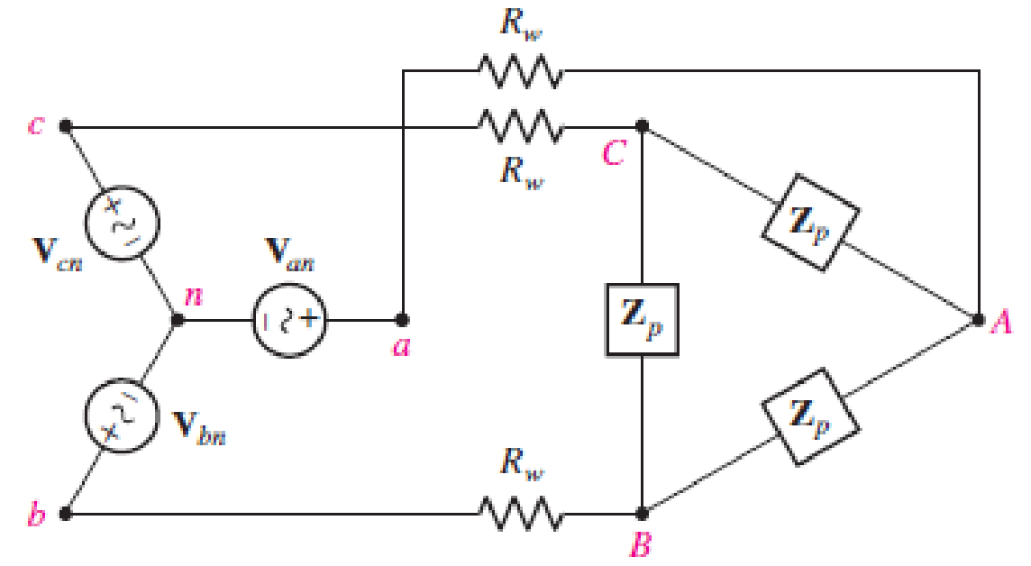
■ FIGURE 12.35
The balanced Δ-connected load in Fig. 12.35 is demanding 10 kVA at a lagging PF of 0.91. If line losses are negligible, calculate IbB and Van if Vca = 160∠30 ° V and the source voltages are described using positive phase sequence.
Expert Solution & Answer
Want to see the full answer?
Check out a sample textbook solution
Students have asked these similar questions
A workshop from a 231/400 V transformer center with a 3-phase and four-conductor underground cablefed. The resistance of the phase conductors is 0.035 ohms and the resistance of the neutral conductors is 0.05 ohms.25 kVA at 0.8 reverse power factor from R phase of the supply line, 0.8 forward power factor from S phase 15Fully ohmic loads of 10 kVA are drawn from kVA and T phases.(a) Find the currents flowing through the phase conductors and neutral conductors.(b) Voltage drops between the transformer substation and the workshop and at the load terminals.calculate the voltages(c) Plot the supply line currents and phase voltages phasorally.
A balanced three-phase Y-connected source
with positive sequance has an internal voltage
of 120 V/phase. The source feeds a balanced
three-phase Y-connected load having an
impedance of 39 + j28 N /phase. The
impedance of the transmission line connecting
the source to the load is 1+ j20/phase. The a-
phase of the source is the reference voltage.
a) Draw the equivalent per-phase-circuit for
the phase "a".
b) Calculate the three line currents in the
transmission lines.
c) Calculate the three phase voltages at load.
d) Calculate the three line-to-line voltages at
the terminals of the load.
e) Calculate the total average power in watts
delivered to the load.
f) Calculate the total complex power in VA
delivered by the source.
V:..
H.W. .mp4
www.DANDICAMCO
H.W. 1 Poly-phase Systems
A three phase, four-wire, 208 volt, CBA system has a wyeconnected load with Z, = 60°,
2, = 6/30° and Ze = 5/45°. Obtain the three line currents and the neutral current(in a polar form)
after finding O2 and 03.
A'
120/03
1002
B-
120/150
Chapter 12 Solutions
Loose Leaf for Engineering Circuit Analysis Format: Loose-leaf
Ch. 12.1 - Let and . Find (a) Vad; (b) Vbc; (c) Vcd.Ch. 12.2 - Prob. 2PCh. 12.2 - Modify Fig. 12.9 by adding a 1.5 resistance to...Ch. 12.3 - A balanced three-phase three-wire system has a...Ch. 12.3 - A balanced three-phase three-wire system has a...Ch. 12.3 - Three balanced Y-connected loads are installed on...Ch. 12.4 - Each phase of a balanced three-phase -connected...Ch. 12.4 - Prob. 8PCh. 12.5 - Determine the wattmeter reading in Fig. 12.24,...Ch. 12.5 - Prob. 10P
Ch. 12 - Prob. 1ECh. 12 - Prob. 2ECh. 12 - Prob. 3ECh. 12 - Describe what is meant by a polyphase source,...Ch. 12 - Prob. 5ECh. 12 - Prob. 6ECh. 12 - Prob. 7ECh. 12 - Prob. 8ECh. 12 - Prob. 9ECh. 12 - Prob. 10ECh. 12 - The single-phase three-wire system of Fig. 12.31...Ch. 12 - Prob. 12ECh. 12 - Referring to the balanced load represented in Fig....Ch. 12 - Prob. 14ECh. 12 - Prob. 15ECh. 12 - Consider a simple positive phase sequence,...Ch. 12 - Assume the system shown in Fig. 12.34 is balanced,...Ch. 12 - Repeat Exercise 17 with Rw = 10 , and verify your...Ch. 12 - Prob. 19ECh. 12 - Prob. 20ECh. 12 - Prob. 21ECh. 12 - Prob. 22ECh. 12 - A three-phase system is constructed from a...Ch. 12 - Prob. 24ECh. 12 - Each load in the circuit of Fig. 12.34 is composed...Ch. 12 - Prob. 26ECh. 12 - Prob. 27ECh. 12 - A three-phase load is to be powered by a...Ch. 12 - For the two situations described in Exercise 28,...Ch. 12 - Prob. 30ECh. 12 - Prob. 31ECh. 12 - Prob. 32ECh. 12 - Repeat Exercise 32 if Rw = 1 . Verify your...Ch. 12 - Prob. 34ECh. 12 - Prob. 35ECh. 12 - Prob. 36ECh. 12 - A wattmeter is connected into the circuit of Fig....Ch. 12 - Find the reading of the wattmeter connected in the...Ch. 12 - (a) Find both wattmeter readings in Fig. 12.39 if...Ch. 12 - Circuit values for Fig. 12.40 are , , , , . Find...Ch. 12 - Prob. 41ECh. 12 - Prob. 42ECh. 12 - (a) Is the load represented in Fig. 12.41...Ch. 12 - Prob. 44E
Knowledge Booster


Learn more about
Need a deep-dive on the concept behind this application? Look no further. Learn more about this topic, electrical-engineering and related others by exploring similar questions and additional content below.Similar questions
- A three-phase balanced Y-connected load with series impedances of (8+ j24) Q per phase and mutual impedance between any two phases of j4 Q is supplied by a three-phase unbalanced source with line-to-neutral voltages of Van = 200/25°, Von = 100/-155°, Ven = 80/100° V. The load and source neutrals are both solidly grounded. Determine: (a) the load sequence impedance matrix, (b) the symmetrical components of the line-to-neutral voltages, (c) the symmetrical components of the load currents, and (d) the load currents. %3Darrow_forwardTwo delta connected loads are connected in parallel and powered by a balanced Y-connectedsource. The smaller of two loads draws 10 kVA at a lagging power factor of 0.75 and the largerdraws 25 kVA at a leading power factor of 0.8. The line voltage is 400 V. Calculate a) The powerfactor at which the source is operating. b) The total power drawn by the two loads. c) The phasecurrent of each load.arrow_forwardProblem 2 For the system shown in Figure 12.5: a) Find Is. b) Find the average power delivered to each element. c) Find the reactive power associated with each element. d) Find PT, QT, and ST. e) Find the power factor seen by the source E. R₁ ww 392 + E = 50 V/60° R3 ww 492 R₂ 12 Ω Χ 16Ω Xc 802 Figure 12.5arrow_forward
- 12. A certain load takes 300 kW at 400 V. A three phase capacitor bank rated 15 kVA per phase is connected in parallel with the load to raise the power factor of the system to 90% lagging. What is the power factor of the load before correction? c. 92% d. 88% a. 99% b. 95% 13. A 132 kV line three phase system delivers 70.7 MVA on a balanced delta connected load of a power factor 70.7% lagging. Determine the reactance necessary to attain unity power factor. a. 1 092 ohms c. 1142 ohms d. 1 045 ohms b. 965 ohms 14. A 150 kVA transformer bank will serve a load expected to draw 135 kW at 0.80 lagging power factor. Solve for the size of the capacitor bank needed to be added in order to prevent overloading of the transformer bank. a 40.391 KVAR d. 28.266 KVAR a. 32.506 KVAR b. 35.866 KVARarrow_forwardCircuit theory I just want the final answer, I don't need the solution steps. I want the solution in less than 30 minutes, please The question is : Q.1) A Y-connected balanced three-phase generator with an impedance of Zs =0.4+j0.3 ohm per phase is connected to a Y-connected balanced load with an impedance of ZL=19+j48 ohm per phase. The line joining the generator and the load has an impedance of Zl=0.6+j0.7 ohm per phase. Assuming a positive sequence for the source voltages and that amplitude of |Van|=204 and its phase angle 30 degree Find: (a) amplitude of the line voltage Vbc, (b) amplitude of the line current Ic, (c) the complex power at the balanced three-phase load. a. (a) Vb=353.34 V, (b) Ic=3.85 A, (c) S = 89641.40 + j 1110.11 VA b. (a) Vb=288.50 V, (b) Ic=2.23 A, (c) S = 14940.23 + j 320.46 VA c. (a) Vb=353.34 V, (b) Ic=3.85 A, (c) S = 846.88 + j 2139.49 VA d. (a) Vb=353.34 V, (b) Ic=5.78 A, (c) S = 44820.70 + j 832.58 VA e. (a) Vb=353.34 V, (b)…arrow_forwardIn a balanced delta connected 3-phase circuit, has resistance 16 ohm and inductive reactance 12 ohm, connected to a 230V,50HZ 3-phase supply voltage, then total power delivered to load is Select one: a. 5397.7W b. 6.34KW c. 16.34KW d. NONE OF THESEarrow_forward
- a. Y-Connected b. В 100kW Source 0.9 LAG 80KVA 0.8 LAG Figure 1 80kW 0.85 LAGarrow_forwardThe following three-phase circuit is symmetrical, with line voltage 220 V, 60 Hz, direct phase sequence, isolated neutral and the value of the impedances of the loads in the three phases are: Zan = 10 ohms Zbn = -10j ohm Zcn = -10j Ohm Find:a) Phase voltages on the load;b) Line and phase currents;c) The power supplied to the load. Consider the phase voltage in the reference(Va voltage angle equal to 0)arrow_forwardThe Figure shows a balanced Y-A 3Ø circuit. The phase voltages of the Y-connected source are V, = 11020°, V, = 1102 - 120° and V. = 1102120°, Volts. The line impdedances are Z,=10+j5 Q each. The impedances of the A-connected load are ZA = 75+j255 N each. Determine: Line Currents, Phase Currents (load), Power drawn by the load. Ve ZA Vbarrow_forward
- A balanced three-phase Y-connected source with positive sequance has an internal voltage of 120 V/phase. The source feeds a balanced three-phase Y-connected load having an impedance of 39 + j28 Ω /phase. The impedance of the transmission line connecting the source to the load is 1 + j2 Ω /phase. The a-phase of the source is the reference voltage. a) Draw the equivalent per-phase-circuit for the phase "a". b) Calculate the three line currents in the transmission lines. c) Calculate the three phase voltages at load. d) Calculate the three line-to-line voltages at the terminals of the load. e) Calculate the total average power in watts delivered to the load. f) Calculate the total complex power in VA delivered by the source.arrow_forwardA balanced three-phase Y-connected source with positive sequance has an internal voltage of 120 V/phase. The source feeds a balanced three-phase Y-connected load having an impedance of 39 + j28 Ω /phase. The impedance of the transmission line connecting the source to the load is 1 + j2 Ω /phase. The a-phase of the source is the reference voltage. a) Draw the equivalent per-phase-circuit for the phase "a". b) Calculate the three line currents in the transmission lines. c) Calculate the three phase voltages at load.arrow_forward1. What is the main direct cause of reactive power in AC system? A. Resistance of transmission lines B. Inductance and capacitance in the loads C. Ideal transformer connected in the system D. Power produced by generator 2. "Reactive power in a system is dissipated generally as thermal energy?" A. TRUE B. FALSE 3. Which of the following statements are correct for three phase circuit: A. Sum of all the three phase currents is zero in unbalanced network B. Total power transfer to load is constant with time C. Neutral conductor is same size in terms of material used as in single phase conductors D. Net apparent power consumed is equal to real powerarrow_forward
arrow_back_ios
SEE MORE QUESTIONS
arrow_forward_ios
Recommended textbooks for you
 Introductory Circuit Analysis (13th Edition)Electrical EngineeringISBN:9780133923605Author:Robert L. BoylestadPublisher:PEARSON
 Delmar's Standard Textbook Of ElectricityElectrical EngineeringISBN:9781337900348Author:Stephen L. HermanPublisher:Cengage Learning
 Programmable Logic ControllersElectrical EngineeringISBN:9780073373843Author:Frank D. PetruzellaPublisher:McGraw-Hill Education
 Fundamentals of Electric CircuitsElectrical EngineeringISBN:9780078028229Author:Charles K Alexander, Matthew SadikuPublisher:McGraw-Hill Education
 Electric Circuits. (11th Edition)Electrical EngineeringISBN:9780134746968Author:James W. Nilsson, Susan RiedelPublisher:PEARSON
 Engineering ElectromagneticsElectrical EngineeringISBN:9780078028151Author:Hayt, William H. (william Hart), Jr, BUCK, John A.Publisher:Mcgraw-hill Education,
Introductory Circuit Analysis (13th Edition)
Electrical Engineering
ISBN:9780133923605
Author:Robert L. Boylestad
Publisher:PEARSON
Delmar's Standard Textbook Of Electricity
Electrical Engineering
ISBN:9781337900348
Author:Stephen L. Herman
Publisher:Cengage Learning
Programmable Logic Controllers
Electrical Engineering
ISBN:9780073373843
Author:Frank D. Petruzella
Publisher:McGraw-Hill Education
Fundamentals of Electric Circuits
Electrical Engineering
ISBN:9780078028229
Author:Charles K Alexander, Matthew Sadiku
Publisher:McGraw-Hill Education
Electric Circuits. (11th Edition)
Electrical Engineering
ISBN:9780134746968
Author:James W. Nilsson, Susan Riedel
Publisher:PEARSON
Engineering Electromagnetics
Electrical Engineering
ISBN:9780078028151
Author:Hayt, William H. (william Hart), Jr, BUCK, John A.
Publisher:Mcgraw-hill Education,
How do Electric Transmission Lines Work?; Author: Practical Engineering;https://www.youtube.com/watch?v=qjY31x0m3d8;License: Standard Youtube License