
Loose Leaf for Engineering Circuit Analysis Format: Loose-leaf
9th Edition
ISBN: 9781259989452
Author: Hayt
Publisher: Mcgraw Hill Publishers
expand_more
expand_more
format_list_bulleted
Concept explainers
Videos
Textbook Question
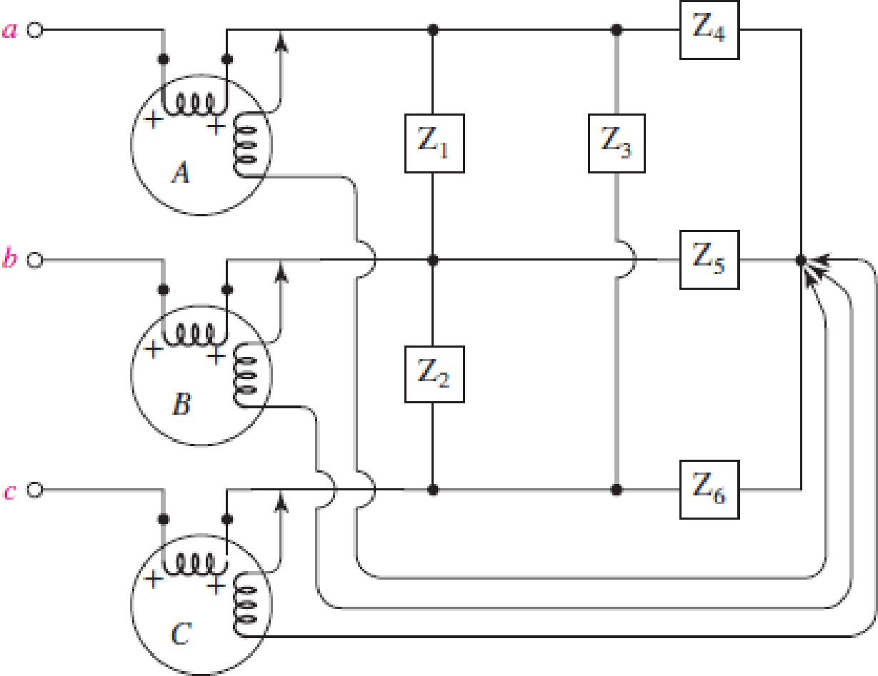
Chapter 12, Problem 40E
Circuit values for Fig. 12.40 are  ,
,  ,
,  ,
,  ,
, 
 . Find the reading for each wattmeter.
Expert Solution & Answer
Want to see the full answer?
Check out a sample textbook solution
Students have asked these similar questions
A resistor, in series with a 138-microfarad capacitor, is connected to a 60-cycle source.If the voltage drop across the capacitor is 115 volts and the power taken by the circuitis 922 watts, calculate (a) the circuit current, (b) the ohmic value of the resistor, (c) theline voltage, (d) the circuit power factor.
draw the circuit diagram
Q2/ Find Yous for the power system all reactance on a common base.
Bus 3
j0.25
j0.10
j0.25
Bus 2
j0.125
Bus 1
j0.40
j0.20
j0.10
Bus 4
Q1. If in one cycle (360 degrees), all of instantaneous power falls under positive loops (no negative loops), the load must be:
a.) a resistor
b.) an inductor or capacitor
Explain:
Q2. A wattmeter will indicate zero when the current lags (or leads) the voltage by 90 degrees. Explain
Chapter 12 Solutions
Loose Leaf for Engineering Circuit Analysis Format: Loose-leaf
Ch. 12.1 - Let and . Find (a) Vad; (b) Vbc; (c) Vcd.Ch. 12.2 - Prob. 2PCh. 12.2 - Modify Fig. 12.9 by adding a 1.5 resistance to...Ch. 12.3 - A balanced three-phase three-wire system has a...Ch. 12.3 - A balanced three-phase three-wire system has a...Ch. 12.3 - Three balanced Y-connected loads are installed on...Ch. 12.4 - Each phase of a balanced three-phase -connected...Ch. 12.4 - Prob. 8PCh. 12.5 - Determine the wattmeter reading in Fig. 12.24,...Ch. 12.5 - Prob. 10P
Ch. 12 - Prob. 1ECh. 12 - Prob. 2ECh. 12 - Prob. 3ECh. 12 - Describe what is meant by a polyphase source,...Ch. 12 - Prob. 5ECh. 12 - Prob. 6ECh. 12 - Prob. 7ECh. 12 - Prob. 8ECh. 12 - Prob. 9ECh. 12 - Prob. 10ECh. 12 - The single-phase three-wire system of Fig. 12.31...Ch. 12 - Prob. 12ECh. 12 - Referring to the balanced load represented in Fig....Ch. 12 - Prob. 14ECh. 12 - Prob. 15ECh. 12 - Consider a simple positive phase sequence,...Ch. 12 - Assume the system shown in Fig. 12.34 is balanced,...Ch. 12 - Repeat Exercise 17 with Rw = 10 , and verify your...Ch. 12 - Prob. 19ECh. 12 - Prob. 20ECh. 12 - Prob. 21ECh. 12 - Prob. 22ECh. 12 - A three-phase system is constructed from a...Ch. 12 - Prob. 24ECh. 12 - Each load in the circuit of Fig. 12.34 is composed...Ch. 12 - Prob. 26ECh. 12 - Prob. 27ECh. 12 - A three-phase load is to be powered by a...Ch. 12 - For the two situations described in Exercise 28,...Ch. 12 - Prob. 30ECh. 12 - Prob. 31ECh. 12 - Prob. 32ECh. 12 - Repeat Exercise 32 if Rw = 1 . Verify your...Ch. 12 - Prob. 34ECh. 12 - Prob. 35ECh. 12 - Prob. 36ECh. 12 - A wattmeter is connected into the circuit of Fig....Ch. 12 - Find the reading of the wattmeter connected in the...Ch. 12 - (a) Find both wattmeter readings in Fig. 12.39 if...Ch. 12 - Circuit values for Fig. 12.40 are , , , , . Find...Ch. 12 - Prob. 41ECh. 12 - Prob. 42ECh. 12 - (a) Is the load represented in Fig. 12.41...Ch. 12 - Prob. 44E
Knowledge Booster


Learn more about
Need a deep-dive on the concept behind this application? Look no further. Learn more about this topic, electrical-engineering and related others by exploring similar questions and additional content below.Similar questions
- A single-phase, 120V(rms),60Hz source supplies power to a series R-L circuit consisting of R=10 and L=40mH. (a) Determine the power factor of the circuit and state whether it is lagging or leading. (b) Determine the real and reactive power absorbed by the load. (c) Calculate the peak magnetic energy Wint stored in the inductor by using the expression Wint=L(Irms)2 and check whether the reactive power Q=Wint is satisfied. (Note: The instantaneous magnetic energy storage fluctuates between zero and the peak energy. This energy must be sent twice each cycle to the load from the source by means of reactive power flows.)arrow_forward1.3 A 240 volts 50 Hz single phase ac source supplies a series load consisting of a resistor (40 ohms), a reactor (127.324 mH) and a capacitor (318.3 µF). Suppose that the frequency of the source can be varied at will. 1.3.1 Determine the maximum load current. 1.3.2 Determine the source frequency for maximum load current. 1.3.3 What is the name of this frequency? 1.3.4 Determine the load power factor. 1.3.5 What is the name of the sourcearrow_forward8. Three generators are rated as follows: Gl: 100MVA, 33kv,Xg1 = 0.1pu. G2: 150MVA,32kv.xg1 0.08pu.G3:110MVA,30kv.xg1 = 0.12pu.Determine the reactance of the generator corresponding to base values of 200MVA and 35kv.arrow_forward
- Two reverse parallel scr are used to control the voltage on a 10 ohm load over a 230V, 50HZ 1- phase AC source, and triggering is done at 3O degrees for positive alterance. Calculate the effective (rms) voltage on the load. a) 230.34V b) 226.64V c) 220V d) 110.56V e) OVarrow_forward3. A step down chopper has Vs = 230 V and R = 10 2. For a duty cycle of 0.4, the power taken by the chopper is 2097 Watts. Find the chopper efficiency. Take the voltage drop across the chopper switch as 2 V. 98 % b) 89.96 % c) 99.14 % d) 96.54 %arrow_forward50. A series resistance-capacitance (R-C) circuit is connected to 230-volt, 50 cycle AC source. The current through the resistor is 45.45 A and the power taken by the circuit is 5,000 watts. Compute the following: a. Ohmic value of the resistor b. Capacitive reactance E. capacitance in microfaradarrow_forward
- P2. A 100 volts rms single-phase voltage source feeds an inductive load of (30+j40) 2. Determine the value of capacitance to bring the power factor of the source to unity.arrow_forwardSample Problems 1. Three identical resistances of 75 ohms are connected in delta across 440 V, 3 phase supply. The value of resistance in each leg of the equivalent star connected load would be ? a) 15 pbmsarrow_forward7. An electromagnet consists of a coil with a laminated core assembly. This device takes 6 A when connected to a 120 V DC course. When energized from a 120 V, 60 Hz AC source, the current is 2 A. The wattmeter reads 100 W. a. Determine the true ohmic resistance of the coil and the effective resistance of the coil. b. Explain why there is a difference between the true ohmic resistance and the effective resistance values for the same coil winding.arrow_forward
- Q1: A 50HZ,11KV,3-ph,alternator with earthed neutral has a reactance of 50\ph and is connected to bus bar through a C.B.The distributed capacitance up to C.B between phase and neutral is 0.01HF,Determine: 1-The restriking voltage across the contacts of the breaker, 2-The frequency of oscillation,and 3-The voltage across the capacitance. (if the disconnecting capacitive tank)? Q2:Repeat (1,2,and 3) in Q1 if the P.F. of the fault was capacitance current breaking due to 0.4? Q3:Repeat (1,2,and 3) in Q1 if the current chops at an instantaneous rate of 8A?arrow_forwardKhalid Abdulrahman Abdullah Alqasmi KA 05 Symm... 9 Search 8 Share O Comments Transitions Animations Slide Show Review View Help 1. A 3- phase, 30 MVA, 33 KV alternator has internal reactance of 4% and negligible resistance. Find the external reactance per phase to be connected in series with the alternator so that steady current on short circuit does not exceed 10 times the full load. Also find Find the full load current. d notesarrow_forwardAn electromagnet consists of a coil with a laminated core assembly. This device takes 6 A when connected to a 120 V DC course. When energized from a 120 V, 60 Hz AC source, the current is 2 A. The wattmeter reads 100 W. Determine the true ohmic resistance of the coil and the effective resistance of the coil. Explain why there is a difference between the true ohmic resistance and the effective resistance values for the same coil windingarrow_forward
arrow_back_ios
SEE MORE QUESTIONS
arrow_forward_ios
Recommended textbooks for you
 Power System Analysis and Design (MindTap Course ...Electrical EngineeringISBN:9781305632134Author:J. Duncan Glover, Thomas Overbye, Mulukutla S. SarmaPublisher:Cengage Learning
Power System Analysis and Design (MindTap Course ...
Electrical Engineering
ISBN:9781305632134
Author:J. Duncan Glover, Thomas Overbye, Mulukutla S. Sarma
Publisher:Cengage Learning
Star Delta Starter Explained - Working Principle; Author: The Engineering Mindset;https://www.youtube.com/watch?v=h89TTwlNnpY;License: Standard Youtube License