
System Dynamics
3rd Edition
ISBN: 9780073398068
Author: III William J. Palm
Publisher: MCG
expand_more
expand_more
format_list_bulleted
Concept explainers
Videos
Textbook Question
Chapter 7, Problem 7.39P
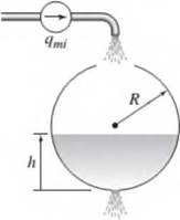
Obtain the dynamic model of the liquid height It in a spherical tank of radius R. shown in Figure P7.39. The mass inflow rate through the top opening is q,„j and the orifice resistance is R„.
Figure P7.39 A spherical tank with an orifice resistance
Expert Solution & Answer
Want to see the full answer?
Check out a sample textbook solution
Students have asked these similar questions
Q.4
A 200 mm diameter pipeline is laid on
the ground. At a particular point, the
piezometric head is 20 m. Total energy head
of water at a point is 26 m. The Discharge
(L/s) of water through the pipe is
Type your answer here..
SUBMIT
EXAMPLE Leaking Tank. Outflow of Water Through a Hole (Torricelli's Law)
This is another prototype engineering problem that leads to an ODE. It concerns the outflow of water from a
cylindrical tank with a hole at the bottom. You are asked to find the height of the water in the tank at any time
if the tank has diameter 2 m, the hole has diameter 1 cm, and the initial height of the water when the hole is
opened is 2.25 m. When will the tank be empty?
2.20 M
Water level
asime
Outiine
walls
200
200
30t
.00-
50-
D
10000
30000
tebe Revelion
50000
A mass weighting 24 lbs stretches a spring 3 inches. The mass is in a medium that exerts a viscous
resistance of 21 lbs when the mass has a velocity of 6 ft/sec.
Suppose the object is displaced an additional 6 inches and released.
Find an equation for the object's displacement, u(t), in feet after t seconds.
u(t) =
Chapter 7 Solutions
System Dynamics
Ch. 7 - Prob. 7.1PCh. 7 - Refer to the water storage and supply system shown...Ch. 7 - Prob. 7.3PCh. 7 - In Figure P7.4 the piston of area A is connected...Ch. 7 - Refer to Figure 7.1.4a. and suppose that p\ — p2=...Ch. 7 - Pure water flows into a mixing tank of volume V =...Ch. 7 - Consider the mixing tank treated in Problem 7.6....Ch. 7 - Derive the expression for the fluid capacitance of...Ch. 7 - Prob. 7.9PCh. 7 - Prob. 7.10P
Ch. 7 - 7.11 Derive the expression for the capacitance of...Ch. 7 - Air flows in a certain cylindrical pipe 1 m long...Ch. 7 - Derive the expression for the linearized...Ch. 7 - Consider the cylindrical container treated in...Ch. 7 - A certain tank has a bottom area A = 20 m2. The...Ch. 7 - A certain tank has a circular bottom area A = 20...Ch. 7 - The water inflow rate to a certain tank was kept...Ch. 7 - Prob. 7.18PCh. 7 - Prob. 7.19PCh. 7 - In the liquid level system shown in Figure P7.20,...Ch. 7 - The water height in a certain tank was measured at...Ch. 7 - Derive the model for the system shown in Figure...Ch. 7 - (a) Develop a model of the two liquid heights in...Ch. 7 - Prob. 7.24PCh. 7 - Design a piston-type damper using an oil with a...Ch. 7 - Prob. 7.26PCh. 7 - 7.27 An electric motor is sometimes used to move...Ch. 7 - Prob. 7.28PCh. 7 - Prob. 7.29PCh. 7 - Figure P7.3O shows an example of a hydraulic...Ch. 7 - Prob. 7.31PCh. 7 - Prob. 7.32PCh. 7 - Prob. 7.33PCh. 7 - Prob. 7.34PCh. 7 - Prob. 7.35PCh. 7 - Prob. 7.36PCh. 7 - Prob. 7.37PCh. 7 - (a) Determine the capacitance of a spherical tank...Ch. 7 - Obtain the dynamic model of the liquid height It...Ch. 7 - Prob. 7.40PCh. 7 - Prob. 7.41PCh. 7 - Prob. 7.42PCh. 7 - Prob. 7.43PCh. 7 - Prob. 7.44PCh. 7 - Prob. 7.45PCh. 7 - The copper shaft shown in Figure P7.46 consists of...Ch. 7 - A certain radiator wall is made of copper with a...Ch. 7 - A particular house wall consists of three layers...Ch. 7 - A certain wall section is composed of a 12 in. by...Ch. 7 - Prob. 7.50PCh. 7 - Prob. 7.51PCh. 7 - A steel tank filled with water has a volume of...Ch. 7 - Prob. 7.53PCh. 7 - Prob. 7.54PCh. 7 - Prob. 7.55P
Knowledge Booster


Learn more about
Need a deep-dive on the concept behind this application? Look no further. Learn more about this topic, mechanical-engineering and related others by exploring similar questions and additional content below.Similar questions
- 4.99 For the system shown in Figure P4.99 the aver- age velocity in the pipe is 10 m/s. Up to point A, K = 1.5, from B to C, K = 6.2, and the pump is 80% efficient. If %3D = 200 kPa find and PB Pc PA %3D and the power required by the pump. Water 10 m Device 30 m 100 mm dia. A B ligut ol bai bns Figure P4.99arrow_forwardQ4: Three pipes A, B and C, are interconnected as shown in figure (4). The pipes characteristics are as follows. L (m) f 600 0.02 B 480 0.032 C 1200 0.042 Find the flow rate at which water will flows in each pipe, also find the pressure at point (P). Pipe EL. 60m Water B Figure (4) D (cm) 15 10 20 P EL.36m C EL.15m waterarrow_forwardSolve problem 2 (Textbook, p. 230). This is a case example how to use the characteristic curve of a pump to find the operation point of a piping installation. You can find the solution graphically, iteratively (if you want to fit the curve of Fig. P4.2 with an equation) or using trial and error (my recommendation). 2. Pump and pipeline—M . The head/discharge curve of a centrifugal pump is shown in Fig. P4.2. The exit of the pump is connected to 1,000 ft of nominal 2-in. diameter horizontal pipe (D = 2.067 in.). What flow rate (ft^3/s) of water can be expected? Assume atmospheric pressure at the pump inlet and pipe exit, and take fF = 0.00475.arrow_forward
- Q.5 A pump circulates water through a closed pipe network connecting a water heater and a heating coil (heat exchanger) in a room. The total length of the pipe is 28 m and the diameter is 32 mm. There are six 90°-elbows and a globe valve in the network. The head loss through the water heater and the heating coil are 1.6 m and 1.2 m respectively. The water flow rate is 0.88 Ls!. The system uses schedule-40 steel pipes with threaded fittings. Calculate the (i) flow velocity and the unit pressure loss in the pipe. (ii) increase in head across the pump. (iii) power input to the pump if the efficiency of the pump is 70%.arrow_forwardThree pipes A, B, and C are interconnected as shown in figure 1. The pipe dimensions are as follows: D (cm) 15 10 20 Pipeline A L (m) 300 240 600 0.01 0.01 0.005 A 15 m 25 m В C Figure 1 1.1 Find the rate at which water will flow in each pipe, ignoring the shock losses at P and entry to pipelines A and B. 1.2 Find the pressure at P.arrow_forwardFor the piping system shown below, water is flowing from left to right at steady-state and constant temperature. You may assume the flow is frictionless. The pipe diameter is larger in section A than section B. The diameters of sections A and C are the same. If gravitation and frictional effects are negligible, which of the following relationships is true about the static pressure in sections A and B? Pc Ps Flow section A section B section C OPA Pg because pressure decreases as velocity increases at steady-state OPA = Pg because friction is assumed to be negligiblearrow_forward
- A process tank has two input streams-Stream 1 at mass flow rate F1 and Stream 2 at mass 1now rate F2. The tank's effluent stream, at flow rate F, discharges through a fixed valve to atmospheric pressure. Pressure drop across the valve is proportional to the flow rate squared. The cross- sectional area of the tank, A, is 5m?, and the mass density of all streams is 940 kg/m³. (a) Draw a schematic diagram of the process and write an appropriate dynamic model for the tank level. What is the corresponding steady-state model? (b) At initial steady-state conditions, with F1 =2.0 kg/s and F2 =1.2 kg/s, the tank level is 2.25 m. What is the value of the valve constant (give units)? (c) A process control engineer decides to use a feed-forward controller to hold the level approximately constant at the set-point value (hsp=2.25 m) by measuring F1 and manipulating F2. What is the mathematical relation that will be used in the controller? If the F1 measurement is not very accurate and always…arrow_forwardThree pipes A, B, and C are interconnected as shown in figure 1. The pipe dimensions are as follows: Pipeline D(cm) L (m) ƒA 15 300 0.01B 10 240 0.01C 20 600 0.005 Find the rate at which water will flow in each pipe, ignoring the shock losses at P and entry to pipelines A and B.arrow_forwardConsider the system presented in the figure x1(t) x2(1) 1 N/m 0000 At) 1 kg 1 N-s/m 1 kg Frictionless The matrix form *+2++1 -(+2) X, (6))(F) X,(s) -(s +2) s +s+1X,(s), F(s) a.arrow_forward
- In this question, assume the "additional displacement" is in the positive u direction. A mass weighing 16 lbs stretches a spring 8 inches. The mass is in a medium that exerts a viscous resistance of 1 lbs when the mass has a velocity of 2 ft/sec. Suppose the object is displaced an additional 5 inches and released. Find an equation for the object's displacement, u(t), in feet after t seconds. u(t) =arrow_forwarda) In an open vessel, a certain volume V of water is perfectly agitated by means of an impeller 20 cm in diameter D. Consider a case in which the impeller steadily rotates at 150 RPM (=revolutions per minute) Draw up a proper energy balance to find how temperature changes with time as a result of the power input øw, also named P, by the revolving impeller. This P is given by the formula P = 3.5 PN³DS in which N denotes the impeller speed in revolutions per second. Calculate P. When V = 120 litre and the specific heat of water amounts to 4.2 kJ/kgK, calculate the temperature increase of the water after one hour of stirring.arrow_forwardP.5.4 A centrifugal pump is used to pump a liquid in steady turbulent flow through a smooth pipe from one tank to another. Develop an expression for the system total head Ah in terms of the static heads on the discharge and suction sides zą and z, respectively, the gas pressures above the tanks on the discharge and suction sides pa and P, respectively, the liquid density p, the liquid dynamic viscosity u, the gravitational acceleration g, the total equivalent lengths on the discharge and suction sides (ELe)a and ELe), respectively, and the volumetric flow rate Q.arrow_forward
arrow_back_ios
SEE MORE QUESTIONS
arrow_forward_ios
Recommended textbooks for you
 Elements Of ElectromagneticsMechanical EngineeringISBN:9780190698614Author:Sadiku, Matthew N. O.Publisher:Oxford University Press
 Mechanics of Materials (10th Edition)Mechanical EngineeringISBN:9780134319650Author:Russell C. HibbelerPublisher:PEARSON
 Thermodynamics: An Engineering ApproachMechanical EngineeringISBN:9781259822674Author:Yunus A. Cengel Dr., Michael A. BolesPublisher:McGraw-Hill Education
 Control Systems EngineeringMechanical EngineeringISBN:9781118170519Author:Norman S. NisePublisher:WILEY
 Mechanics of Materials (MindTap Course List)Mechanical EngineeringISBN:9781337093347Author:Barry J. Goodno, James M. GerePublisher:Cengage Learning
 Engineering Mechanics: StaticsMechanical EngineeringISBN:9781118807330Author:James L. Meriam, L. G. Kraige, J. N. BoltonPublisher:WILEY
Elements Of Electromagnetics
Mechanical Engineering
ISBN:9780190698614
Author:Sadiku, Matthew N. O.
Publisher:Oxford University Press
Mechanics of Materials (10th Edition)
Mechanical Engineering
ISBN:9780134319650
Author:Russell C. Hibbeler
Publisher:PEARSON
Thermodynamics: An Engineering Approach
Mechanical Engineering
ISBN:9781259822674
Author:Yunus A. Cengel Dr., Michael A. Boles
Publisher:McGraw-Hill Education
Control Systems Engineering
Mechanical Engineering
ISBN:9781118170519
Author:Norman S. Nise
Publisher:WILEY
Mechanics of Materials (MindTap Course List)
Mechanical Engineering
ISBN:9781337093347
Author:Barry J. Goodno, James M. Gere
Publisher:Cengage Learning
Engineering Mechanics: Statics
Mechanical Engineering
ISBN:9781118807330
Author:James L. Meriam, L. G. Kraige, J. N. Bolton
Publisher:WILEY
Fluid Mechanics - Viscosity and Shear Strain Rate in 9 Minutes!; Author: Less Boring Lectures;https://www.youtube.com/watch?v=_0aaRDAdPTY;License: Standard youtube license