
Shigley's Mechanical Engineering Design (McGraw-Hill Series in Mechanical Engineering)
10th Edition
ISBN: 9780073398204
Author: Richard G Budynas, Keith J Nisbett
Publisher: McGraw-Hill Education
expand_more
expand_more
format_list_bulleted
Concept explainers
Videos
Textbook Question
Chapter 4, Problem 9P
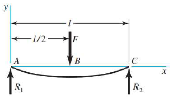
Derive the equations given for beam 5 in Table A–9 using statics and the double-integration method.
5 Simple supports—center load
Expert Solution & Answer
Want to see the full answer?
Check out a sample textbook solution
Students have asked these similar questions
THE ORIGINAL QUESTION IS: For the beam shown, find the reactions at the supports and plot the shear-force and bending-moment diagrams. Label the diagrams properly and provide values at all key points. THE QUESTION THAT NEEDS TO BE ANSWERED IS:
Repeat problem 3-5 using singularity functions exclusively (including reactions).
Link 2, shown in the figure, is 25 mm wide and 11 mm thick. It is made from low-carbon steel with Sy= 165 MPa. The pin joints are constructed with sufficient size and fit to provide good resistance to out-of-plane bending. Use Table 4-2 shown below for recommended values for C. Determine the following for link 2:
a.)Axial Force
b.)Yield factor of safety
c.) In-plane buckling factor of safety and Out-plane buckling factor of safety
A beam 19 ft in length has concentrated live loads of 6 kips and 9 kips at 5 ft and 13 ft, respectively, from the left-hand support. In addition, there is a uniformly distributed dead load of 1.2 kips/ft beginning 5 ft from the left support and continuing to the right support. Design the beam for flexure.
Chapter 4 Solutions
Shigley's Mechanical Engineering Design (McGraw-Hill Series in Mechanical Engineering)
Ch. 4 - The figure shows a torsion bar OA fixed at O,...Ch. 4 - For Prob. 41, if the simple support at point A...Ch. 4 - A torsion-bar spring consists of a prismatic bar,...Ch. 4 - An engineer is forced by geometric considerations...Ch. 4 - A bar in tension has a circular cross section and...Ch. 4 - Prob. 6PCh. 4 - Prob. 7PCh. 4 - Derive the equations given for beam 2 in Table A9...Ch. 4 - Derive the equations given for beam 5 in Table A9...Ch. 4 - The figure shows a cantilever consisting of steel...
Ch. 4 - A simply supported beam loaded by two forces is...Ch. 4 - Using superposition, find the deflection of the...Ch. 4 - A rectangular steel bar supports the two...Ch. 4 - An aluminum tube with outside diameter of 2 in and...Ch. 4 - The cantilever shown in the figure consists of two...Ch. 4 - Using superposition for the bar shown, determine...Ch. 4 - A simply supported beam has a concentrated moment...Ch. 4 - Prob. 18PCh. 4 - Using the results of Prob. 418, use superposition...Ch. 4 - Prob. 20PCh. 4 - Consider the uniformly loaded simply supported...Ch. 4 - Prob. 22PCh. 4 - Prob. 23PCh. 4 - Prob. 24PCh. 4 - Prob. 25PCh. 4 - Prob. 26PCh. 4 - Prob. 27PCh. 4 - Prob. 28PCh. 4 - 429 to 434 For the steel countershaft specified in...Ch. 4 - Prob. 30PCh. 4 - Prob. 31PCh. 4 - Prob. 32PCh. 4 - For the steel countershaft specified in the table,...Ch. 4 - For the steel countershaft specified in the table,...Ch. 4 - Prob. 35PCh. 4 - Prob. 36PCh. 4 - Prob. 37PCh. 4 - Prob. 38PCh. 4 - Prob. 39PCh. 4 - Prob. 40PCh. 4 - The cantilevered handle in the figure is made from...Ch. 4 - Prob. 42PCh. 4 - The cantilevered handle in Prob. 384, p. 154, is...Ch. 4 - A flat-bed trailer is to be designed with a...Ch. 4 - The designer of a shaft usually has a slope...Ch. 4 - Prob. 46PCh. 4 - If the diameter of the steel beam shown is 1.25...Ch. 4 - For the beam of Prob. 4-47, plot the magnitude of...Ch. 4 - Prob. 49PCh. 4 - 4-50 and 4-51 The figure shows a rectangular...Ch. 4 - and 451 the ground at one end and supported by a...Ch. 4 - The figure illustrates a stepped torsion-bar...Ch. 4 - Consider the simply supported beam 5 with a center...Ch. 4 - Prob. 54PCh. 4 - Prob. 55PCh. 4 - Solve Prob. 410 using singularity functions. Use...Ch. 4 - Prob. 57PCh. 4 - Prob. 58PCh. 4 - Prob. 59PCh. 4 - Solve Prob. 413 using singularity functions. Since...Ch. 4 - Prob. 61PCh. 4 - Solve Prob. 419 using singularity functions to...Ch. 4 - Using singularity functions, write the deflection...Ch. 4 - Determine the deflection equation for the...Ch. 4 - Use Castiglianos theorem to verify the maximum...Ch. 4 - Use Castiglianos theorem to verify the maximum...Ch. 4 - Solve Prob. 415 using Castiglianos theorem.Ch. 4 - Solve Prob. 452 using Castiglianos theoremCh. 4 - Determine the deflection at midspan for the beam...Ch. 4 - Using Castiglianos theorem, determine the...Ch. 4 - Solve Prob. 441 using Castiglianos theorem. Since...Ch. 4 - Solve Prob. 442 using Castiglianos theorem.Ch. 4 - The cantilevered handle in Prob. 384 is made from...Ch. 4 - Solve Prob. 450 using Castiglianos theorem.Ch. 4 - Solve Prob. 451 using Castiglianos theorem.Ch. 4 - The steel curved bar shown has a rectangular cross...Ch. 4 - Repeat Prob. 476 to find the vertical deflection...Ch. 4 - For the curved steel beam shown. F = 6.7 kips....Ch. 4 - A steel piston ring has a mean diameter of 70 mm....Ch. 4 - For the steel wire form shown, use Castiglianos...Ch. 4 - 4-81 and 4-82 The part shown is formed from a...Ch. 4 - 4-81 and 4-82 The part shown is formed from a...Ch. 4 - Repeat Prob. 481 for the vertical deflection at...Ch. 4 - Repeat Prob. 482 for the vertical deflection at...Ch. 4 - A hook is formed from a 2-mm-diameter steel wire...Ch. 4 - The figure shows a rectangular member OB, made...Ch. 4 - Prob. 87PCh. 4 - For the wire form shown, determine the deflection...Ch. 4 - Prob. 89PCh. 4 - Prob. 90PCh. 4 - Prob. 91PCh. 4 - Prob. 92PCh. 4 - Solve Prob. 492 using Castiglianos method and...Ch. 4 - An aluminum step bar is loaded as shown. (a)...Ch. 4 - The steel shaft shown in the figure is subjected...Ch. 4 - Repeat Prob. 495 with the diameters of section OA...Ch. 4 - The figure shows a 12- by 1-in rectangular steel...Ch. 4 - For the beam shown, determine the support...Ch. 4 - Solve Prob. 498 using Castiglianos theorem and...Ch. 4 - Consider beam 13 in Table A9, but with flexible...Ch. 4 - Prob. 101PCh. 4 - The steel beam ABCD shown is simply supported at C...Ch. 4 - Prob. 103PCh. 4 - A round tubular column has outside and inside...Ch. 4 - For the conditions of Prob. 4104, show that...Ch. 4 - Link 2, shown in the figure, is 25 mm wide, has...Ch. 4 - Link 3, shown schematically in the figure, acts as...Ch. 4 - The hydraulic cylinder shown in the figure has a...Ch. 4 - The figure shows a schematic drawing of a...Ch. 4 - If drawn, a figure for this problem would resemble...Ch. 4 - Design link CD of the hand-operated toggle press...Ch. 4 - Find the maximum values of the spring force and...Ch. 4 - As shown in the figure, the weight W1 strikes W2...Ch. 4 - Part a of the figure shows a weight W mounted...
Knowledge Booster


Learn more about
Need a deep-dive on the concept behind this application? Look no further. Learn more about this topic, mechanical-engineering and related others by exploring similar questions and additional content below.Similar questions
- A vertical channel 152 x 76 (see Table A-7) has a cantilever beam bolted to it as shown. The channel is hot-rolled AISI 1006 steel. The bar is of hot-rolled AISI 1015 steel. The shoulder bolts are M10 x 1.5 ISO 5.8. Assume the bolt threads do not extend into the joint. For a design factor of 2.2, find the safe force Fthat can be applied to the cantilever. 12 50 +50--50-- 26! 125 The maximum allowable force on the system Fis N.arrow_forwardClasswork Problem 2 Draw the Shear Force Diagram (SFD) and Bending Moment Diagram (BMD) for a loaded simply supported beam shown below 1KN 5kN 2kN 4KN 1m 1m 2m 1m 1m 14arrow_forwardFigure P3-36 shows a beam made from 4 in schedule 40 steel pipe. Compute the deflection at points A and B for two cases: (a) the simple cantilever and (b) the supported cantilever. -6 ft. +4 ft → 800 lb B -8 ft- (a) Simple cantilever 800 lb B -10 ft- Support (b) Supported cantileverarrow_forward
- Bolts distributed about a bolt circle are often called upon to resist an external bending moment as shown in the figure. The external moment is 19 kip-in and the bolt circle has a diameter of 15 in. The neutral axis for bending is a diameter of the bolt circle. What needs to be determined is the most severe external load seen by a bolt in the assembly. M Neutral axis R NOTE: This is a multi-part question. Once an answer is submitted, you will be unable to return to this part. View the effect of the bolts as placing a line load around the bolt circle whose intensity FÅ, in pounds per inch, varies linearly with the distance from the neutral axis according to the relation Fb Fb,max R sin 8. The load on any particular bolt can be viewed as the effect of the line load over the arc associated with the bolt. For example, there are 12 bolts shown in the figure. Thus, each bolt load is assumed to be distributed on a 30° arc of the bolt circle. Under these conditions, what is the largest bolt…arrow_forwardFIGURE PS-55 25 K 15 K 6 ft 4 ft 3.0K/ft 4 Use the free body diagram pproach shown in Sections 5-3 through 5-5 to determin the internal shearing force and bending moment al any speecified point in a beam. nd bending moneat diagrams using the guidelines pre- sented in Section 5-10.arrow_forwardRepeat Problem 11.3-9. Use two C 150 × 12.2 steel shapes and assume that E = 205 GPa and L = 6 m.arrow_forward
- Compare the angle of twist 1 for a thin-walled circular tube (see figure) calculated from the approximate theory for thin-walled bars with the angle of twist 2 calculated from the exact theory of torsion for circular bars, Express the ratio 12terms of the non-dimensional ratio ß = r/t. Calculate the ratio of angles of twist for ß = 5, 10, and 20. What conclusion about the accuracy of the approximate theory do you draw from these results?arrow_forwardSolve Problem 11.3-3 for a W 10 × 45 steel column having a length L = 28 ft.arrow_forwardRepeat Problem 9,5-15 for the anti-symmetric loading shown in the figure.arrow_forward
- A seesaw weighing 3 lb/ft of length is occupied by two children, each weighing 90 lb (see figure). The center of gravity of each child is 8 ft from the fulcrum. The board is 19 ft long, 8 in. wide, and 1.5 in. thick. What is the maximum bending stress in the board?arrow_forwardRepeat Problem 11.2-3 assuming that R= 10 kN · m/rad and L = 2 m.arrow_forward-15 A composite beam is constructed froma wood beam (3 in. x 6 in.) and a steel plate (3 in, wide). The wood and the steel are securely fastened to act as a single beam. The beam is subjected to a positive bending moment M. = 75 kip-in. Calculate the required thickness of the steel plate based on the following limit states: Allowable compressive stress in the wood = 2 ksi Allowable tensile stress in the wood = 2 ksi Allowable tensile stress in the steel plate = 16 ksi Assume that Ew= 1,500 ksi and es= 30,000 ksi.arrow_forward
arrow_back_ios
SEE MORE QUESTIONS
arrow_forward_ios
Recommended textbooks for you
 Mechanics of Materials (MindTap Course List)Mechanical EngineeringISBN:9781337093347Author:Barry J. Goodno, James M. GerePublisher:Cengage Learning
Mechanics of Materials (MindTap Course List)
Mechanical Engineering
ISBN:9781337093347
Author:Barry J. Goodno, James M. Gere
Publisher:Cengage Learning
Solids: Lesson 53 - Slope and Deflection of Beams Intro; Author: Jeff Hanson;https://www.youtube.com/watch?v=I7lTq68JRmY;License: Standard YouTube License, CC-BY