
Shigley's Mechanical Engineering Design (McGraw-Hill Series in Mechanical Engineering)
10th Edition
ISBN: 9780073398204
Author: Richard G Budynas, Keith J Nisbett
Publisher: McGraw-Hill Education
expand_more
expand_more
format_list_bulleted
Concept explainers
Videos
Textbook Question
Chapter 4, Problem 108P
The hydraulic cylinder shown in the figure has a 2-in bore and is to operate at a pressure of 1500 psi. With the clevis mount shown, the piston rod should be sized as a column with both ends rounded for any plane of buckling. The rod is to be made of forged AISI 1030 steel without further heat treatment.
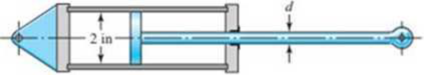
Problem 4-108
- (a) Use a design factor nd = 2.5 and select a preferred size for the rod diameter if the column length is 50 in.
- (b) Repeat part (a) but for a column length of 16 in.
- (c) What factor of safety actually results for each of the cases above?
Expert Solution & Answer
Want to see the full answer?
Check out a sample textbook solution
Students have asked these similar questions
The hydraulic cylinder shown in the figure has a 2-in bore and is to operate at a pressure of 1500 psi. With the
clevis mount shown, the piston rod should be sized as a column with both ends rounded for any plane of
buckling. The rod is to be made of forged AISI 1030 steel without further heat treatment resulting in yield
strength of 37.5 kpsi, and Young's modulus of 30 mpsi.
Problem 4-131
(a) Use a design factor na = 2.5 and select a preferred size for the rod diameter if the column length is 50 in.
(b) Repeat part (a) but for a column length of 16 in.
(c) What factor of safety actually results for each of the cases above?
The figure below shows a boat propeller mounted on a drive shaft with a 7 mm diameter (d) cylindrical drive pin inserted through the hub
and the shaft. The drive shaft diameter, D, inside the hub is 69 mm. The pin is made from AISI 1020 cold rolled steel, which has a yield stress
of 427 MPa and an ultimate stress of 621 MPa. If the drive pin is subjected to an overload (e.g. strikes a log), calculate the torque (Nm)
required to shear the pin.
Note: Assume that the max shear stress of the pin material is approximately equal 82% of the ultimate tensile stress.
Do not include units in your answer.
Pin
F
Hub
Drive
pin
Shaft
Drive
shaft
F
Shear
planes
Hub
Answer:
PROBLEM:1 A gas engine valve spring is to have a mean diameter of 55 mm. The
maximum load it will have to sustain is 584 N with a corresponding deflection of 7.18
mm. The spring is to be made of tempered wire. Since the material is to be subjected
to repeated loading and fatigue must be considered a low working stress of 650
N/mm? will be used. Find the size for wire and number of coils used. Take modulus of
rigidity as 0.84 x 10⁵ N/mm? .Assume the spring coil is squared and ground. Take
shear stress Concentration factor as 1.15.
Chapter 4 Solutions
Shigley's Mechanical Engineering Design (McGraw-Hill Series in Mechanical Engineering)
Ch. 4 - The figure shows a torsion bar OA fixed at O,...Ch. 4 - For Prob. 41, if the simple support at point A...Ch. 4 - A torsion-bar spring consists of a prismatic bar,...Ch. 4 - An engineer is forced by geometric considerations...Ch. 4 - A bar in tension has a circular cross section and...Ch. 4 - Prob. 6PCh. 4 - Prob. 7PCh. 4 - Derive the equations given for beam 2 in Table A9...Ch. 4 - Derive the equations given for beam 5 in Table A9...Ch. 4 - The figure shows a cantilever consisting of steel...
Ch. 4 - A simply supported beam loaded by two forces is...Ch. 4 - Using superposition, find the deflection of the...Ch. 4 - A rectangular steel bar supports the two...Ch. 4 - An aluminum tube with outside diameter of 2 in and...Ch. 4 - The cantilever shown in the figure consists of two...Ch. 4 - Using superposition for the bar shown, determine...Ch. 4 - A simply supported beam has a concentrated moment...Ch. 4 - Prob. 18PCh. 4 - Using the results of Prob. 418, use superposition...Ch. 4 - Prob. 20PCh. 4 - Consider the uniformly loaded simply supported...Ch. 4 - Prob. 22PCh. 4 - Prob. 23PCh. 4 - Prob. 24PCh. 4 - Prob. 25PCh. 4 - Prob. 26PCh. 4 - Prob. 27PCh. 4 - Prob. 28PCh. 4 - 429 to 434 For the steel countershaft specified in...Ch. 4 - Prob. 30PCh. 4 - Prob. 31PCh. 4 - Prob. 32PCh. 4 - For the steel countershaft specified in the table,...Ch. 4 - For the steel countershaft specified in the table,...Ch. 4 - Prob. 35PCh. 4 - Prob. 36PCh. 4 - Prob. 37PCh. 4 - Prob. 38PCh. 4 - Prob. 39PCh. 4 - Prob. 40PCh. 4 - The cantilevered handle in the figure is made from...Ch. 4 - Prob. 42PCh. 4 - The cantilevered handle in Prob. 384, p. 154, is...Ch. 4 - A flat-bed trailer is to be designed with a...Ch. 4 - The designer of a shaft usually has a slope...Ch. 4 - Prob. 46PCh. 4 - If the diameter of the steel beam shown is 1.25...Ch. 4 - For the beam of Prob. 4-47, plot the magnitude of...Ch. 4 - Prob. 49PCh. 4 - 4-50 and 4-51 The figure shows a rectangular...Ch. 4 - and 451 the ground at one end and supported by a...Ch. 4 - The figure illustrates a stepped torsion-bar...Ch. 4 - Consider the simply supported beam 5 with a center...Ch. 4 - Prob. 54PCh. 4 - Prob. 55PCh. 4 - Solve Prob. 410 using singularity functions. Use...Ch. 4 - Prob. 57PCh. 4 - Prob. 58PCh. 4 - Prob. 59PCh. 4 - Solve Prob. 413 using singularity functions. Since...Ch. 4 - Prob. 61PCh. 4 - Solve Prob. 419 using singularity functions to...Ch. 4 - Using singularity functions, write the deflection...Ch. 4 - Determine the deflection equation for the...Ch. 4 - Use Castiglianos theorem to verify the maximum...Ch. 4 - Use Castiglianos theorem to verify the maximum...Ch. 4 - Solve Prob. 415 using Castiglianos theorem.Ch. 4 - Solve Prob. 452 using Castiglianos theoremCh. 4 - Determine the deflection at midspan for the beam...Ch. 4 - Using Castiglianos theorem, determine the...Ch. 4 - Solve Prob. 441 using Castiglianos theorem. Since...Ch. 4 - Solve Prob. 442 using Castiglianos theorem.Ch. 4 - The cantilevered handle in Prob. 384 is made from...Ch. 4 - Solve Prob. 450 using Castiglianos theorem.Ch. 4 - Solve Prob. 451 using Castiglianos theorem.Ch. 4 - The steel curved bar shown has a rectangular cross...Ch. 4 - Repeat Prob. 476 to find the vertical deflection...Ch. 4 - For the curved steel beam shown. F = 6.7 kips....Ch. 4 - A steel piston ring has a mean diameter of 70 mm....Ch. 4 - For the steel wire form shown, use Castiglianos...Ch. 4 - 4-81 and 4-82 The part shown is formed from a...Ch. 4 - 4-81 and 4-82 The part shown is formed from a...Ch. 4 - Repeat Prob. 481 for the vertical deflection at...Ch. 4 - Repeat Prob. 482 for the vertical deflection at...Ch. 4 - A hook is formed from a 2-mm-diameter steel wire...Ch. 4 - The figure shows a rectangular member OB, made...Ch. 4 - Prob. 87PCh. 4 - For the wire form shown, determine the deflection...Ch. 4 - Prob. 89PCh. 4 - Prob. 90PCh. 4 - Prob. 91PCh. 4 - Prob. 92PCh. 4 - Solve Prob. 492 using Castiglianos method and...Ch. 4 - An aluminum step bar is loaded as shown. (a)...Ch. 4 - The steel shaft shown in the figure is subjected...Ch. 4 - Repeat Prob. 495 with the diameters of section OA...Ch. 4 - The figure shows a 12- by 1-in rectangular steel...Ch. 4 - For the beam shown, determine the support...Ch. 4 - Solve Prob. 498 using Castiglianos theorem and...Ch. 4 - Consider beam 13 in Table A9, but with flexible...Ch. 4 - Prob. 101PCh. 4 - The steel beam ABCD shown is simply supported at C...Ch. 4 - Prob. 103PCh. 4 - A round tubular column has outside and inside...Ch. 4 - For the conditions of Prob. 4104, show that...Ch. 4 - Link 2, shown in the figure, is 25 mm wide, has...Ch. 4 - Link 3, shown schematically in the figure, acts as...Ch. 4 - The hydraulic cylinder shown in the figure has a...Ch. 4 - The figure shows a schematic drawing of a...Ch. 4 - If drawn, a figure for this problem would resemble...Ch. 4 - Design link CD of the hand-operated toggle press...Ch. 4 - Find the maximum values of the spring force and...Ch. 4 - As shown in the figure, the weight W1 strikes W2...Ch. 4 - Part a of the figure shows a weight W mounted...
Knowledge Booster


Learn more about
Need a deep-dive on the concept behind this application? Look no further. Learn more about this topic, mechanical-engineering and related others by exploring similar questions and additional content below.Similar questions
- Repeat Problem 10.3-15 using L = 3.5 m, max = 3 mm, and EI = 800 kN·m2.arrow_forwardRepeat Problem 2.3-4, but now include the weight of the bar. Sec Table 1.1 in Appendix I for the weight density of steel.arrow_forwardSolve Problem 11.3-3 for a W 10 × 45 steel column having a length L = 28 ft.arrow_forward
- Repeat Problem 11.2-3 assuming that R= 10 kN · m/rad and L = 2 m.arrow_forwardRepeat Problem 3.3-1, but now use a circular tube with outer diameter d0= 2.5 in. and inner diameter di= 1.5 in.arrow_forwardA crank arm consists of a solid segment of length bxand diameter rf, a segment of length bltand a segment of length byas shown in the figure. Two loads P act as shown: one parallel to — vand another parallel to —y. Each load P equals 1.2 kN. The crankshaft dimensions are A] = 75 mm, fr> = 125 mm, and b3= 35 mm. The diameter of the upper shaft isd = 22 mm, (a) Determine the maximum tensile, compressive, and shear stresses at point A, which is located on the surface of the shaft at the z axis. (b) Determine the maximum tensile, compressive, and shear stresses at point B, which is located on the surface of the shaft at the y axisarrow_forward
- Repeat Problem 11.2-14 using L = 12 ft, ß = 0.25 kips/in., ßRl= 1.5ßL2, and ßR2= 2 ßR1.arrow_forwardA hydraulic cylinder with a bore radius of 100 mm and an outer radius of 200 mmhas been designed to withstand a maximum internal pressure of 200 MPa inservice. During operation, the pressure within the cylinder is retained by a freelysliding piston. The steel used in the manufacture has Young’s modulus of 210GNm-2. In an alternative design, the cylinder has been constructed as a compoundcylinder (duplex cylinder) with the same bore and outer radii by shrink-fitting twotubes of the same steel. The nominal radius at the common interface is 150 mmand the radial interference (shrinkage allowance, δ) is 100 μm (micro-meters).a) Determine using Lame’s equations, the radial and circumferentialstresses at the cylinder bore, common interface, and outer surface.b) Graphically present (sketch) the variation of each of these stresses acrossthe cylinder wall, clearly indicating the values at the inner and outer surfacesof each cylinder.c) Draw the Mohr's circles representing the stresses acting on…arrow_forwardFigure below shows a portion of a pump that is gear-driven at uniform load and speed. The 25 mm diameter solod shaft supported by the bearings is to be made of machined AISI 1045 CD steel. The helical gear is subjected to the axial force F =499 y a radial load F = 741 N and a tangential load of F=2,006 N. Assume the component is operating at room temperature of 70°F and the material has 50% reliability factor. 25-mm solid Bending K, = 2.0 round shaft Fillet Torsional K = 1.5 F. F, Axial K, = 1.8 F Pump Helical spur gear 50 mm -250-mm dia.- FIGURE 1. Identify the critical location(s) of stress and show it clearly in a diagram. 2. Identify cleary, all the components of stresses (at the critical point) that will be calculated (by drawing and clearly showing the XYZ axes) and show it in a matrix form. Show which components of stresses will have a value zero or non-zero. 3. Calculate the principal stresses and principal directions. Show the principal stresses clearly in a stress element…arrow_forward
- Calculate the dimensions of the I-section of a connecting rod, stating any assumptions. using the data below: Maximum cylinder pressure = 3.15N/mm² Cylinder bore = 100mm Factor of Safety=6 Crank length 95mm Connecting rod length=380mm Take the constant a=7500.arrow_forwardThe chain drive is mounted in the center for the system shown in figure.It can transmit 15 hp at a speed of 400 rpm and the sprocket has a pitch diameter of 6 inches. The shaft is made of ASTM-A 709 Grade 50 steel. A factor of safety of 2.5 is required. Is the design acceptable? Hint: You need to calculate torsion and bending stresses during solution.arrow_forwardQ3/ Design a helical compression spring made from stainless steel for the following operating conditions: Spring load when the valve is open = 600 N, Spring load when the valve is closed = 250 N, Maximum inside diameter of spring = 25 mm, Length of the spring when the valve is open = 40 mm, Length of the spring when the valve is closed = 50 mm, take into account the Wahl stress factor.arrow_forward
arrow_back_ios
SEE MORE QUESTIONS
arrow_forward_ios
Recommended textbooks for you
 Mechanics of Materials (MindTap Course List)Mechanical EngineeringISBN:9781337093347Author:Barry J. Goodno, James M. GerePublisher:Cengage Learning
Mechanics of Materials (MindTap Course List)
Mechanical Engineering
ISBN:9781337093347
Author:Barry J. Goodno, James M. Gere
Publisher:Cengage Learning
Fire Safety; Author: Toronto Metropolitan University;https://www.youtube.com/watch?v=7jCyJIJllHE;License: Standard Youtube License