
Concept explainers
Videos
The slope of the shaft at each bearing.
Answer to Problem 32P
The slope of the shaft at bearing point O is
Explanation of Solution
The figure below shows the free body diagram of pulley A.
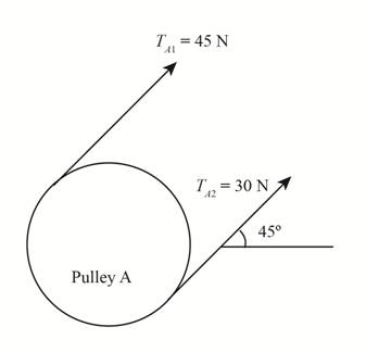
Figure (1)
The figure below shows the free body diagram of pulley B.
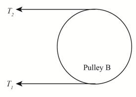
Figure (2)
The given assumption is that the belt tension on the loose side is
Write the expression for the tensions on the loose side in terms of tension on the tight side.
Here, the tension on the tight side is
Write the equation to balance the tension on the counter shaft.
Here, the tension on the tight side of pulley
Substitute
Write the expression for net applied load at point A.
Here, the tension force exerted by the pulley at each side at point A are
Write the expression for net applied load at point B.
Here, the tension force exerted by the pulley at each side at point B are
Write the equation for moment of inertia of the shaft.
Here, the diameter of the shaft is
The free body diagram of the beam in the direction of y-axis is shown below.
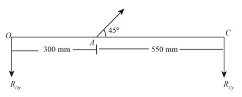
Figure (3)
Write the equation for force component along y-axis.
Here, the net force at point A is
Write the equation for force component along z-axis.
Write the deflection equation for portion OA using Table A-9 for beam 6.
Here, Young’s modulus of the shaft material is
Substitute
Write the expression for net slope of the shaft at point O along z-axis.
Substitute
The free body diagram of the beam in the direction of z-axis is shown below.
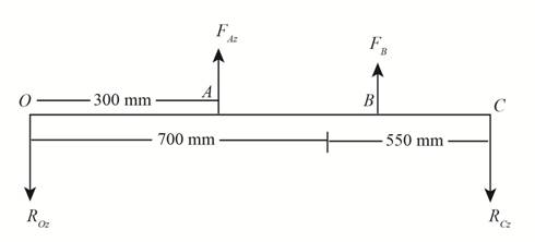
Figure (4)
Write the deflection equation along z-axis using Table A-9 for beam 6.
Here, the force component along z-axis is
Write the expression for net slope of the shaft at point O along y-axis.
Substitute
Substitute
Write the expression for net slope at point O.
Write the deflection equation for portion BC using Table A-9 for beam 6.
Here, the location of applied point load at point A from left end bearing point O is
Write the expression for net slope of the shaft at point C along z-axis.
Substitute
Substitute
Write the deflection equation for portion BC using Table A-9 for beam 6.
Here, the location of applied point load at point B from left end bearing point O is
Write the expression for net slope of the shaft at point C along y-axis.
Substitute the value of
Substitute
Write the expression for net slope at point C.
Conclusion:
Substitute
Substitute
Substitute
Substitute
Substitute
Substitute
Thus, the slope of the shaft at bearing point O along z-axis is
Substitute
Thus, the slope of the shaft at bearing point O along y-axis is
Substitute
Thus, the net slope of the shaft at bearing point O is
Substitute
Thus, the slope of the shaft at bearing point C along z-axis is
Substitute
Thus, the slope of the shaft at bearing point C along y-axis is
Substitute
Thus, the net slope of the shaft at bearing point C is
Want to see more full solutions like this?
Chapter 4 Solutions
Shigley's Mechanical Engineering Design (McGraw-Hill Series in Mechanical Engineering)


- Compare the angle of twist 1 for a thin-walled circular tube (see figure) calculated from the approximate theory for thin-walled bars with the angle of twist 2 calculated from the exact theory of torsion for circular bars, Express the ratio 12terms of the non-dimensional ratio ß = r/t. Calculate the ratio of angles of twist for ß = 5, 10, and 20. What conclusion about the accuracy of the approximate theory do you draw from these results?arrow_forwardA statically indeterminate stepped shaft ACE is fixed at ends A and B and loaded by a torque TQat point C (see figure). The two segments of the bar are made of the same material, have lengths L4and LB, and have polar moments of inertia IAand Ipb. Determine the angle of rotation 4>of the cross section at Cby using strain energy. Hint: Use Eq, (3-55b) to determine the strain energy Urn terms of the angle d?. Then equate the strain energy to the work done by the torque to. Compare your result with Eq. (3-52) of Example 3-9.arrow_forwardRepeat Problem 10.4-41 for the loading shown in the figure.arrow_forward
- Repeat Problem 11.3-9. Use two C 150 × 12.2 steel shapes and assume that E = 205 GPa and L = 6 m.arrow_forwardThe Z-section of Example D-7 is subjected to M = 5 kN · m, as shown. Determine the orientation of the neutral axis and calculate the maximum tensile stress c1and maximum compressive stress ocin the beam. Use the following numerical data: height; = 200 mm, width ft = 90 mm, constant thickness a = 15 mm, and B = 19.2e. Use = 32.6 × 106 mm4 and I2= 2.4 × 10e mm4 from Example D-7arrow_forwardThe non prismatic, cantilever circular bar shown has an internal cylindrical hole from 0 to y, so the net polar moment of inertia of the cross section for segment 1 is (7/8 )Ip. Torque Tis applied at _y and torque 772 is applied at .v = L. Assume that G is constant. Find the reaction moment Ry. Find internal torsional moments Tiin segments 1 and 2. Find x required to obtain twist at joint 3 of tf3 = TLtGIp. What is the rotation at joint 2, Draw the torsional moment (TMD:7(.,0 _v L) and displacement (TDD: M_y),0 x L) diagrams.arrow_forward
- Solve the preceding problem for a steel pipe column (E = 210 GPa) with length L = 1.2 m, inner diameter d2= 36 mm, and outer diameter d2=40 mm.arrow_forwardSolve the preceding problem for a W 200 × 41,7 shape with h = 166 mm, h = 205 mm. rw = 7.24 mm, tE= ILS mm,andV = 38 kN.arrow_forwardSolve the preceding problem for the following data:P = 160 kN,JV = 200 tN,L = 2 m,b = 95 mm, h = 300 mm, and d = 200 mmarrow_forward
- A solid circulai' aluminum bar AB is fixed at both ends and loaded by a uniformly distributed torque 150N·n/m. The bar has diameter d = 30 mm. Calculate the reactive torques at the supports and the angle of twist at midspan. Assume that G = 28 GPa.arrow_forwardRepeat Problem 9,5-15 for the anti-symmetric loading shown in the figure.arrow_forwardThe cross section of a sign post of constant thickness is shown in the figure. Derive the formula for the distance e from the cent crime of the wall of the post to the shear center S: where I2. = moment of inertia about the z axis. Also, compare this formula with that given in Problem 6.9-11 for the special case of ß = 0 here and a = h/2 in both formulas.arrow_forward
 Mechanics of Materials (MindTap Course List)Mechanical EngineeringISBN:9781337093347Author:Barry J. Goodno, James M. GerePublisher:Cengage Learning