
Shigley's Mechanical Engineering Design (McGraw-Hill Series in Mechanical Engineering)
10th Edition
ISBN: 9780073398204
Author: Richard G Budynas, Keith J Nisbett
Publisher: McGraw-Hill Education
expand_more
expand_more
format_list_bulleted
Videos
Textbook Question
Chapter 10, Problem 9P
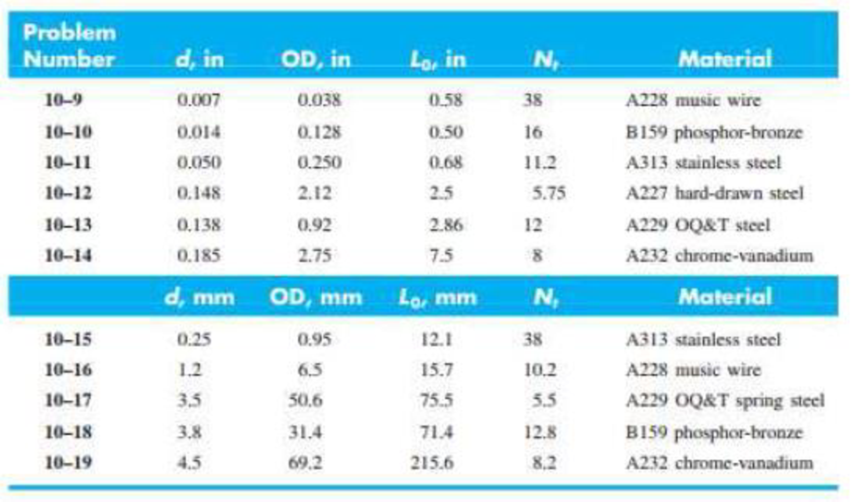
10–9 to 10–19 Listed in the tables are six springs described in customary units and five springs described in SI units. Investigate these squared-and-ground-ended helical compression springs to see if they are solid-safe. If not, what is the largest free length to which they can be wound using ns = 1.2?
Expert Solution & Answer
Want to see the full answer?
Check out a sample textbook solution
Students have asked these similar questions
Investigate the helical compression springs with squared and ground ends fabricated from A313 stainless steel to see if
they are solid safe. If not, what is the largest free length to which they can be wound using ng = 1.2? Given: d= 0.0508 in,
OD = 0.249 in, Nt = 11.2 coils, and Lo= 0.72 in.
NOTE: This is a multi-part question. Once an answer is submitted, you will be unable to return to this part.
Determine the values of the solid height, Ls, the spring rate, k, and the shear stress.
The solid height, Ls, is
.569 in.
The spring rate, k, is
Ibf/in.
The shear stress is
kpsi.
The free end of a torsional spring deflects through 90° when subjected to a torque of 4 N-m. The spring index
is 6. Determine the coil wire diameter and number of turns with the following data :
Modulus of rigidity 80 GPa ; Modulus of elasticity = 200 GPa; Allowable stress = 500 MPa.
Example 8-4
in SI Units.
• Q-2 Figure gives the cross section of a
grade 25 cast-iron pressure vessel. A
total of N bolts are to be used to resist a M16 x 2 x 60 mm class 5.8
separating force of 36 kip (160.2 kN).
• (a) Determine k,, Kmy and C.
• (b) Find the number of bolts required for
a load factor of 2 where the bolts may be
reused when the joint is taken apart.
hexagonal head bolt
No: 25 CI
20 mm
20 mm
• (c) With the number of bolts obtained in
part (b), determine the realized load
factor for overload, the yielding factor of
safety, and the load factor for joint
separation.
H = 14.8 mm
Chapter 10 Solutions
Shigley's Mechanical Engineering Design (McGraw-Hill Series in Mechanical Engineering)
Ch. 10 - Within the range of recommended values of the...Ch. 10 - It is instructive to examine the question of the...Ch. 10 - A helical compression spring is wound using...Ch. 10 - The spring in Prob. 10-3 is to be used with a...Ch. 10 - A helical compression spring is made with...Ch. 10 - A helical compression spring is to be made of...Ch. 10 - A helical compression spring is made of hard-drawn...Ch. 10 - The spring of Prob. 107 is to be used with a...Ch. 10 - 109 to 1019 Listed in the tables are six springs...Ch. 10 - 109 to 1019 Listed in the tables are six springs...
Ch. 10 - 10-9 to 10-19 Listed in the tables are six springs...Ch. 10 - Prob. 12PCh. 10 - 10-9 to 10-19 Listed in the tables are six springs...Ch. 10 - 10-9 to 10-19 Listed in the tables are six springs...Ch. 10 - 10-9 to 10-19 Listed in the tables are six springs...Ch. 10 - 10-9 to 10-19 Listed in the tables are six springs...Ch. 10 - Prob. 17PCh. 10 - 10-9 to 10-19 Listed in the tables are six springs...Ch. 10 - 10-9 to 10-19 Listed in the tables are six springs...Ch. 10 - Consider the steel spring in the illustration. (a)...Ch. 10 - A static service music wire helical compression...Ch. 10 - Solve Prob. 1021 by iterating with an initial...Ch. 10 - A holding fixture for a workpiece 37.5 mm thick at...Ch. 10 - Solve Prob. 10-23 by iterating with an initial...Ch. 10 - A compression spring is needed to fit over a...Ch. 10 - A compression spring is needed to fit within a...Ch. 10 - A helical compression spring is to be cycled...Ch. 10 - The figure shows a conical compression helical...Ch. 10 - A helical coil compression spring is needed for...Ch. 10 - Solve Prob. 10-30 using the Goodman-Zimmerli...Ch. 10 - Solve Prob. 10-30 using the Sines-Zimmerli...Ch. 10 - Design the spring of Ex. 10-5 using the...Ch. 10 - Solve Prob. 10-33 using the Goodman-Zimmerli...Ch. 10 - A hard-drawn spring steel extension spring is to...Ch. 10 - The extension spring shown in the figure has...Ch. 10 - Design an infinite-life helical coil extension...Ch. 10 - Prove Eq. (10-40). Hint: Using Castigliunos...Ch. 10 - The figure shows a finger exerciser used by...Ch. 10 - The rat trap shown in the figure uses two...Ch. 10 - Prob. 41PCh. 10 - Prob. 42PCh. 10 - Figure 10-13b shows a spring of constant thickness...
Knowledge Booster


Learn more about
Need a deep-dive on the concept behind this application? Look no further. Learn more about this topic, mechanical-engineering and related others by exploring similar questions and additional content below.Similar questions
- What is the design stress in psi of an ASTM A313, gage number 8 spring wire. The type of application requires a factor of 0.34 for the type of service. Round your answer to 4 significant figures.arrow_forwardTwo plates are clamped by a 3/4-10 UNC SAE Grade 5 bolt and regular nut with a 3/4-W plain washer as shown in figure. Top plate is made of grey cast iron and bottom plate is steel. An axial force of 12kN is acted upon the joint. Round off the length of the bolt to nearest 1/4in. Assume bolts are preloaded to 75% of proof load. 1. Determine the bolt stiffness kb. 2. Determine the member stiffness km. 3. Determine the yielding factor of safety of the bolt. 4. Determine the load factor for the bolt. 5. Determine the load factor guarding against joint separation. 1.25 in 1.00 inarrow_forwardProblem 4: A helical compression spring is to be cycled between 150 lbf and 300 lbf with a 1-in stroke. The number of cycles is low, so fatigue is not an issue. The coil must fit in a 2.1-in diameter hole with a 0.1-in clearance all the way around the spring. Use unpeened music wire with squared and ground ends. (a) Determine a suitable wire diameter, using a spring index of C = 7. (b) Determine a suitable mean coil diameter. (c) Determine the necessary spring constant. (d) Determine a suitable total number of coils. (e) Determine the necessary free length so that if the spring were compressed to its solid length, there would be no yieldingarrow_forward
- M P 1: Y A :s.google.com Q1 * Find the number of bolts M8 1 which made from SAE Grade 4 steel that should be used to provide a clamping force of 60 KN between two components of a machine. Also, specify the required tightening torque. (Hint: assume that cach bolt is limited to be stressed to 65% of its proof strength). 1 Add file Q2 * A flat plate with a central hole is subjected to an axial tensile force F of 9.8 KN, as shown in the figure below. Calculate the minimum thickness t of the plate. Given that the material of the plate can support maximum tensile stress of 75 N.mm, w = 10 cm and d = 3 cm. Thickness =t F 1 Add file Submit Clear form IIarrow_forwardCalculate the wire diameter of a helical spring using Wahl's factor if the load applied is 130 lb and spring index is 8, if the maximum shearing stress is 50 ksi.arrow_forwardThe load on a helical spring is 1282 lb and the corresponding deflection is to be 3.4 inches. Rigidity modulus is 11 x 106 psi and the maximum intensity of safe torsional stress is 60,000 psi. If the wire diameter and the mean diameter are 0.5 in. and 3 in., respectively. Determine the number of active coils. Don't round your answer to preferred size. Round your answer to 4 significant figuresarrow_forward
- Calculate the maximum tensile stress developed in a 1/4-20 bolt (Major dia = 0.2500" and Root dia = 0.1959"), 3" long, and a head height of 0.1875", if it is subjected to a load of 426 lbs.arrow_forwardQestion-1: A 9/16 in UNF bolt is subjected to a load P = 60 kip in a tension joint as shown in Figure. The bolt is SAE grade 5 and lubricated. The initial bolt tension (F) = 35 kip. The bolt and joint stiffnesses are k, = 6.5 and km 10.8 Mlbf/in Note: Use the related tables, formulas and concepts to answer following question (a) Formulate to determine the preload and service load stresses in the bolt. (b) Solve to find the torque necessary to develop the preload. (c) Identify if the bolt will fail or no under preload and service load stresses (Calculated in part a) by comparing with the SAE minimum proof strength of the bolt. (d) Can you identify; with given input data, tables and formulas that bolt is self-locking? Table 8-9 SAE Specifications for Steel Bolts Size SAE Range Grade Inclusive, No. in +14 1 2 4 5 5.2 7 8 TI I LI I I I +-14 8.2 -1 Minimum Proof Strength," kpsi 33 55 33 65 85 74 85 105 120 120 Table 8-2 Diameters and Area of Unified Screw Threads Size Designation 0 1 2 3 4…arrow_forwardCondition #1: A structural support for a machine is subjected to a static compression load of 20 kN. The support is manufactured from a circular rod made from SAE 1040 Hot Rolled steel. Specify suitable diameter for the cross section of the rod based on the basic size. Steel data are available in Table A-10 from the textbook. Condition #2: The same structural support of the basic size determined in Condition 1 is subjected to a tensile load of 15 kN that is repeated several thousand times over the life of the machine. This load is not an addition to the 20 kN. Specify a suitable steel that is suitable to this application based on the basic size determined in Condition #1. Loading of Condition #1 does not apply here. Condition #3: The same structural support from Condition 2 is heated from room temperature of 25°C. The support is placed inside a frame on both ends. There is a total clearance of 0.2 mm between the support and its frame. Initial length of the rod is 200 mm. Specify the…arrow_forward
- Use the drawing below to answer the following two questions. a. Determine the equivalent spring stiffness of the following system. Simplify the expression (ie – single common denominator. Your answer should be an expression of just K’s – no numbers). b. If the weight on top is 20 lb and the K1 = K4 = 50 lb/in, K2 = 33 lb/in and K3 = K5 = 25 lb/in, what is the natural frequency of the system?arrow_forwardA part is loaded with a combination of bending, axial, and torsion such that the following stresses are created at a particular location: Bending - Completely reversed, with a maximum stress of 60 MPa Axial - Constant stress of 20 MPa Torsion - Repeated load, varying from 0 MPa to 50 MPa Assume the varying stresses are in phase with each other. The part contains a notch such that Kibending = 1.4, Kaxial = 1.1, and K. = 2.0. The material properties are Sy = 300 MPa and S, = 400 MPa. The completely adjusted endurance limit is found to be Se= 200 MPa. Find the factor of safety for fatigue based on infinite life. If the life is not infinite, estimate the number of cycles. Be sure to check for yielding. f,torsionarrow_forwardA spring made from music wire ASTM 228 steel has the following data:Free length=1.75” Outside diameter=0.561”Wire diameter=0.055” Applied load= 14 lbEnds=square and ground both ends hingedNumber of coils=10 G=11.85 x 10⁶psi E= 30 Mpsi Findspring rate, force at solid length,check for buckling,coil clearance and hole diameterarrow_forward
arrow_back_ios
SEE MORE QUESTIONS
arrow_forward_ios
Recommended textbooks for you
 Mechanics of Materials (MindTap Course List)Mechanical EngineeringISBN:9781337093347Author:Barry J. Goodno, James M. GerePublisher:Cengage Learning
Mechanics of Materials (MindTap Course List)
Mechanical Engineering
ISBN:9781337093347
Author:Barry J. Goodno, James M. Gere
Publisher:Cengage Learning
Mechanical SPRING DESIGN Strategy and Restrictions in Under 15 Minutes!; Author: Less Boring Lectures;https://www.youtube.com/watch?v=dsWQrzfQt3s;License: Standard Youtube License