
Concept explainers
Videos
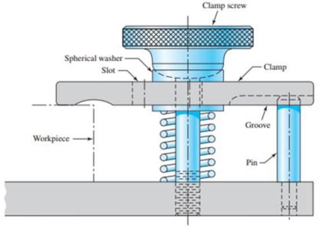
A holding fixture for a workpiece 37.5 mm thick at the clamp locations is being designed. The detail of one of the clamps is shown in the figure. A spring is required to drive the clamp upward when removing the workpiece with a starting force of 45 N. The clamp screw has an M10 × 1.25 thread. Allow a diametral clearance of 1.25 mm between it and the uncompressed spring. It is further specified that the free length of the spring should be L0 ≤ 48 mm, the solid height Ls ≤ 31.5 mm, and the safety factor when closed solid should be ns ≥ 1.2. Starting with d = 2 mm. design a suitable helical coil compression spring for this fixture. For A227 HD steel, wire diameters are available in 0.2-mm increments between 0.2 to 3.2 mm.
Problem 10-23
Clamping fixture.
Want to see the full answer?
Check out a sample textbook solution
Chapter 10 Solutions
Shigley's Mechanical Engineering Design (McGraw-Hill Series in Mechanical Engineering)


- In a bolted joint two members are connected with an axial tightening force of 2200 N. If the bolt used has metric threads of 4 mm pitch, the torque required for achieving the tightening force isarrow_forwardL21. Figure P4-21 shows an anvil for an impact hammer held in a fixture by a circular pin. If the force is to be 500 lb, specify a suitable diameter for the steel pin if it is to be made from SAE 1040 WQT 900. 4-21arrow_forwardThe open V-belt drive system shown in Figure 3 has a groove angle of 30° and is used as a speed booster. The input shaft rotates at 500 rpm and has a sheave with a pitch diameter of 7.218 in and the output shaft has a sheave with a pitch diameter of 3.609 in. The center distance between the two shafts is 15.01 in. The coefficient of friction is 0.25 and the maximum tension in the tight side of the belt is 300 lb. Determine; The maximum power transmitted by the belt if its mass is 0.04 slug/ft. [Hint: P 8 (T-T2)xv P in horse power (hp), T, and T, in (lb). v in (ft/min)]. 33000 Belts and Chains 4-d. sin-4-d, 20arrow_forward
- The open V-belt drive system shown in Figure 3 has a groove angle of 30° and is used as a speed booster. The input shaft rotates at 500 rpm and has a sheave with a pitch diameter of 7.218 in and the output shaft has a sheave with a pitch diameter of 3.609 in. The center distance between the two shafts is 15.01 in. The coefficient of friction is 0.25 and the maximum tension in the tight side of the belt is 300 lb. Determine; 1. The angular velocity of the output shaft. 2. The belt wrap on the input and output sheaves. 3. The belt perimeter length. 4. The length of span between sheaves. 5. The maximum power transmitted by the belt if its mass is 0.04 slug/ft. [Hint: P 8 (T-T2)xv P in horse power (hp), T, and T, in (lb). v in (ft/min)]. 33000 Belts and Chains 4-d. sin-4-d, 20 Figure 3arrow_forwardThe figure shows a schematic drawing of a vehicular jack that is to be designed to support a maximum mass of 300 kg based on the use of a design factor na = 3.50. The opposite-handed threads on the two ends of the screw are cut to allow the link angle 0 to vary from 15 to 70°. The links are to be machined from AISI 1010 hot-rolled steel bars. Each of the four links is to consist of two bars, one on each side of the central bearings. The bars are to be 350 mm long and have a bar width of w = 30 mm. The pinned ends are to be designed to secure an end-condition constant of at least C = 1.4 for out-of-plane buckling. Find a suitable preferred thickness and the resulting factor of safety for this thickness. W 華 warrow_forwardSolve the problem. A 11-in. connecting rod in an engine connects the wrist pin of a piston at point A to the end of a second rod at point on the crankshaft. As the piston moves forward and back, the crankshaft is turned counterclockwise around point C. The stroke length of the engine is the distance that the piston travels (one way) with its cylinder. If the stroke length is 4 in., and the engine turns at 600 rpm, write a model representing the distance d (in inches) from A to the center of the crankshaft Cas a function of time t (in minutes). Assume that at t = 0, the piston is at its farthest point from the crankshaft. B B C C B A A stroke lengtharrow_forward
- 10-23 Problem 10-23 Clamping fixture. A holding fixture for a workpiece 37.5 mm thick at the clamp locations is being designed. The detail of one of the clamps is shown in the figure. A spring is required to drive the clamp upward when removing the workpiece with a starting force of 45 N. The clamp screw has an M10 X 1.25 thread. Allow a diametral clearance of 1.25 mm between it and the uncompressed spring. It is further specified that the free length of the spring should be Lo ≤ 48 mm, the solid height L, 31.5 mm, and the safety factor when closed solid should be n, 1.2. Starting with d = 2 mm, design a suitable helical coil compression spring for this fixture. For A227 HD steel, wire diameters are available in 0.2-mm increments between 0.2 to 3.2 mm. Clamp screw Spherical washer Slot Workpiece Clamp Groove Pinarrow_forwardIn the figure below the clamping force on the pipe is (331.7 lb), knowing that a single threaded screw Acme with major diameter (1 in) is used with coefficient of friction (0.2135). If booth screw and nut are made from 1030 - hot rolled Carbon Steel. Determine: 1- The tightening and loosening torques. 2- Thread screw and nut shear safety factors in case of double threads are in engagement. 3.3 in 2 7.2 in 32 3 in hingearrow_forwardUse the drawing below to answer the following two questions. a. Determine the equivalent spring stiffness of the following system. Simplify the expression (ie – single common denominator. Your answer should be an expression of just K’s – no numbers). b. If the weight on top is 20 lb and the K1 = K4 = 50 lb/in, K2 = 33 lb/in and K3 = K5 = 25 lb/in, what is the natural frequency of the system?arrow_forward
- Information about the clamp assembly in the figure is given below. Thread diameter 12 mm, root diameter 10.16 mm, pitch 1.5 mm, screw profile angle 2α=60, friction surface of table A diameter 10 mm, friction between plate A-screw end surface coefficient 0.15 and screw-nut friction coefficient 0.15 is given. If a hand force of 200N is applied to the vise arm, if applied, a) How much force is applied to the clamped part. b) Calculate the efficiency of the vise.arrow_forwardA bolt with a square threaded screw has mean diameter of 25 mm and a pitch of 3 mm. It carries an axial thrust of 10 kN on the bolt head of 25 mm mean radius. If u = 0.12, find the force required at the end of a spanner 450 mm long, in tightening up the bolt. 3. [Ans. 110.8 N] A turn buckle with right and left hand threads is used to counle twvo railway coaches The threadsarrow_forwardSolve the following problems as stated below. Draw the figure and FBD. PROBLEM A flanged bolt coupling consist of 9 steel bolts evenly spaced around a bolt circle 300 mm. in diameter and 6 bronze bolts on a concentric bplt circle 200 mm. in diameter. What are the sizes of bolts diameters for steel and bronze, if the torque applied is 6,000 N-m and without exceeding the stress of 60 MPa in the steel and 40 MPa for the bronze? The ratio of the bolt diameter d, / ds = 0.50. For steel, use Gs = 83 GPa and for bronze, G, = 28 Gpa. %3D Rs Rparrow_forward
 Mechanics of Materials (MindTap Course List)Mechanical EngineeringISBN:9781337093347Author:Barry J. Goodno, James M. GerePublisher:Cengage Learning