
Shigley's Mechanical Engineering Design (McGraw-Hill Series in Mechanical Engineering)
10th Edition
ISBN: 9780073398204
Author: Richard G Budynas, Keith J Nisbett
Publisher: McGraw-Hill Education
expand_more
expand_more
format_list_bulleted
Videos
Textbook Question
Chapter 10, Problem 40P
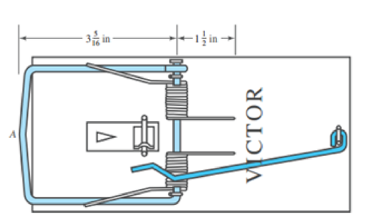
The rat trap shown in the figure uses two opposite-image torsion springs. The wire has a diameter of 0.081 in. and the outside diameter of the spring in the position shown is
- (a) Find the probable configuration of the spring prior to assembly.
- (b) Find the maximum stress in the spring when the trap is set.
Expert Solution & Answer
Want to see the full answer?
Check out a sample textbook solution
Chapter 10 Solutions
Shigley's Mechanical Engineering Design (McGraw-Hill Series in Mechanical Engineering)
Ch. 10 - Within the range of recommended values of the...Ch. 10 - It is instructive to examine the question of the...Ch. 10 - A helical compression spring is wound using...Ch. 10 - The spring in Prob. 10-3 is to be used with a...Ch. 10 - A helical compression spring is made with...Ch. 10 - A helical compression spring is to be made of...Ch. 10 - A helical compression spring is made of hard-drawn...Ch. 10 - The spring of Prob. 107 is to be used with a...Ch. 10 - 109 to 1019 Listed in the tables are six springs...Ch. 10 - 109 to 1019 Listed in the tables are six springs...
Ch. 10 - 10-9 to 10-19 Listed in the tables are six springs...Ch. 10 - Prob. 12PCh. 10 - 10-9 to 10-19 Listed in the tables are six springs...Ch. 10 - 10-9 to 10-19 Listed in the tables are six springs...Ch. 10 - 10-9 to 10-19 Listed in the tables are six springs...Ch. 10 - 10-9 to 10-19 Listed in the tables are six springs...Ch. 10 - Prob. 17PCh. 10 - 10-9 to 10-19 Listed in the tables are six springs...Ch. 10 - 10-9 to 10-19 Listed in the tables are six springs...Ch. 10 - Consider the steel spring in the illustration. (a)...Ch. 10 - A static service music wire helical compression...Ch. 10 - Solve Prob. 1021 by iterating with an initial...Ch. 10 - A holding fixture for a workpiece 37.5 mm thick at...Ch. 10 - Solve Prob. 10-23 by iterating with an initial...Ch. 10 - A compression spring is needed to fit over a...Ch. 10 - A compression spring is needed to fit within a...Ch. 10 - A helical compression spring is to be cycled...Ch. 10 - The figure shows a conical compression helical...Ch. 10 - A helical coil compression spring is needed for...Ch. 10 - Solve Prob. 10-30 using the Goodman-Zimmerli...Ch. 10 - Solve Prob. 10-30 using the Sines-Zimmerli...Ch. 10 - Design the spring of Ex. 10-5 using the...Ch. 10 - Solve Prob. 10-33 using the Goodman-Zimmerli...Ch. 10 - A hard-drawn spring steel extension spring is to...Ch. 10 - The extension spring shown in the figure has...Ch. 10 - Design an infinite-life helical coil extension...Ch. 10 - Prove Eq. (10-40). Hint: Using Castigliunos...Ch. 10 - The figure shows a finger exerciser used by...Ch. 10 - The rat trap shown in the figure uses two...Ch. 10 - Prob. 41PCh. 10 - Prob. 42PCh. 10 - Figure 10-13b shows a spring of constant thickness...
Knowledge Booster


Learn more about
Need a deep-dive on the concept behind this application? Look no further. Learn more about this topic, mechanical-engineering and related others by exploring similar questions and additional content below.Similar questions
- A polyethylene tube (length L) has a cap that when installed compresses a spring (with under-formed length L1) by an amount ?? = (L1 = L). Ignore deformations of the cap and base. Use the force at the base of the spring as the redundant. Use numerical properties given in the boxes. (a) What is the resulting Force-in the spring, Fk? (b) What is the resulting Force in the tube, Ftl (c) What is the filial length of the tube, Lf? (d) What temperature change ?T inside the tube will result in zero force in the springarrow_forwardA small lab scale has a rigid L-shaped frame ABC consisting of a horizontal arm AB (length b = 10 in.) and a vertical arm BC (length c = 7 in.) pivoted al point B. The pivot is attached to the outer frame BCD that stands on a laboratory bench. The position of the pointer al C is controlled by a spring, Jt = 5 lb/in., that is attached to a threaded rod. The pitch of the threads is p = 1/16 in. Under application of load W, 12 revolutions of the nut are required to bring the pointer back to the mark. Calculate the weight W.arrow_forwardCompare the angle of twist 1 for a thin-walled circular tube (see figure) calculated from the approximate theory for thin-walled bars with the angle of twist 2 calculated from the exact theory of torsion for circular bars, Express the ratio 12terms of the non-dimensional ratio ß = r/t. Calculate the ratio of angles of twist for ß = 5, 10, and 20. What conclusion about the accuracy of the approximate theory do you draw from these results?arrow_forward
- A small lab scale has a rigid L-shaped frame ABC consisting of a horizontal aim AB (length b = 30 cm) and a vertical arm BC (length c = 20 cm) pivoted at point B. The pivot is attached to the outer frame BCD that stands on a laboratory bench. The position of the pointer at C is controlled by two parallel springs, each having a spring constant k = 3650 N/m. that are attached to a threaded rod. The pitch of the threads is p = 1.5 mm. If the weight is 65 N. how many revolutions of the nut are required to bring the pointer back to the mark?arrow_forward-19 The mechanical assembly shown in the figure consists of an aluminum tube, a rigid end plate, and two steel cables. The slack is removed from the cables by rotating the turnbuckles until the assembly is snug but with no initial stresses. Afterward, the turnbuckles are tightened by 1.5 turns. Calculate the forces in the tube and the cables and determine the shortening of the tube. As= 0.85 in2 for each cable, AA= 4.5 in2, L = 20 in., Es= 29,000 ksi, EA= 10,600 ksi, and p = 1/16 inarrow_forwardA bumping post at the end of a track in a railway yard has a spring constant k = 8.0 MN/m (see figure). The maximum possible displacement d or the end of the striking plate is 450 mm. What is the maximum velocity vmaxthat a railway car of weight W = 545 kN can have without damaging the bumping post when it strikes it?arrow_forward
- Repeat Problem 11.2-3 assuming that R= 10 kN · m/rad and L = 2 m.arrow_forwardPipe 2 has been inserted snugly into Pipe I. but the holes Tor a connecting pin do not line up; there is a gap s. The user decides to apply either force P:lo Pipe I or force P-, to Pipe 2, whichever is smaller. Determine the following using the numerical properties in the box. (a) If only P{is applied, find Pt{tips} required to close gap s; if a pin is then inserted and Ptremoved, what are reaction forces RAand RBfor this load case? (b) If only P2is applied, find P2{kips) required to close gap a; if a pin is inserted and P2removed, what are reaction forces R^ and RBfor this load case? (c) What is the maximum shear stress in the pipes, for the loads in parts (a) and (b)? (d) If a temperature increase IT is to be applied to the entire structure to close gaps{instead of applying forces Ptand P2), find the AT required to close the gap. If a pin is inserted after the gaphas closed, what are reaction forces .''.', and RBfor this case? (e) Finally, if the structure (with pin inserted) then cools to the original ambient temperature, what are reaction forces Rtand Parrow_forwardThe piston in an engine is attached to a connecting rod AB, which in turn is connected to a crank arm BC (see figure). The piston slides without friction in a cylinder and is subjected to a force P (assumed to be constant) while moving to the right in the Figure. The connecting rod. with diameter d and length L, is attached at both ends by pins. The crank arm rotates about the axle at C with the pin at B moving in a circle of radius R. The axle at C, which is supported by bearings, exerts a resisting moment M against the crank arm. (a) Obtain a formula for the maximum permissible force Pallow. based upon an allowable compressive stress acin the connecting rod. (b) Calculate the Force Pallowfor the following data:arrow_forward
- The inclined ladder AB supports a house painter (85 kg) at C and the weight iq = 40 K/m} of the ladder itself. Each ladder rail (t5= 4 mm) is supported by a shoe (ts= 5 mm) that is attached to the ladder rail by a bolt of diameter d = 8 mmarrow_forwardTwo steel wines support a moveable overhead camera weighing W = 28 lb (see figure part a) used For close-up to viewing of field action at sporting, events. At some instant, wire I is at an angle a = 22° to the horizontal and wire 2 is at angle fi = 40°. Wires I and 2 have diameters of 30and 35 mils, respectively. (Wire diameters are often expressed in mils; one mil equals 0.001 in.) (a) Determine the tensile stresses s and s2 in the two wires. (b) If the stresses in wires 1 and 2 must be the same, what is the required diameter of wire 1 ? (c) To stabilize the camera for windy outdoor conditions, a third wire is added (see figure part b). Assume the three wires meet at a common point coordinates (0, 0. 0) above the camera at the instant shown in figure part b. Wire I is attached to a support at coordinates (75 ft, 48 ft, 70 Ft). Wire 2 is supported at (-70 ft. 55 ft, 80 Ft). Wire 3 is supported at (-10 ft. -85 Ft, 75 ft). Assume that all three wires have a diameter of 30 mils. Find the tensile stresses in all three wiresarrow_forwardA cable and pulley system in the figure part a supports a cage of a mass 300 kg at B. Assume that this includes the mass of the cables as well. The thickness or each of the three steel pulleys is t = 40 mm. The pin diameters are dPA= 25 mm, dB= 30 mm. and dc= 22 mm (see figure part a and part b). (a) Find expressions for the resultant forces acting on the pulleys at A, B. and C in terms of cubic tension T. (b) What is the maximum weight W that can be added to the cage at B based on the following allowable stresses? Shear stress in the pins is 50 MPa; bearing stress between the pin and the pulley is 110 MPa.arrow_forward
arrow_back_ios
SEE MORE QUESTIONS
arrow_forward_ios
Recommended textbooks for you
 Mechanics of Materials (MindTap Course List)Mechanical EngineeringISBN:9781337093347Author:Barry J. Goodno, James M. GerePublisher:Cengage Learning
Mechanics of Materials (MindTap Course List)
Mechanical Engineering
ISBN:9781337093347
Author:Barry J. Goodno, James M. Gere
Publisher:Cengage Learning
Mechanical SPRING DESIGN Strategy and Restrictions in Under 15 Minutes!; Author: Less Boring Lectures;https://www.youtube.com/watch?v=dsWQrzfQt3s;License: Standard Youtube License