
Mechanics of Materials (10th Edition)
10th Edition
ISBN: 9780134319650
Author: Russell C. Hibbeler
Publisher: PEARSON
expand_more
expand_more
format_list_bulleted
Concept explainers
Videos
Textbook Question
Chapter 4.5, Problem 4.43P
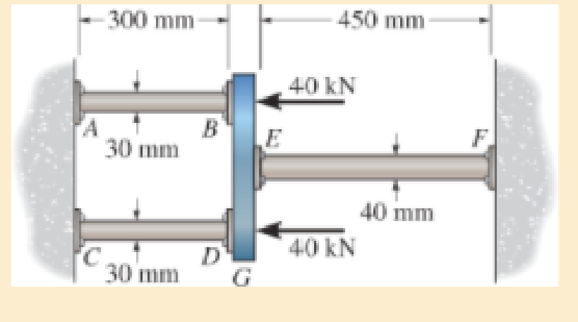
The assembly consists of two red brass C83400 copper rods AB and CD of diameter 30 mm, a stainless 304 steel alloy rod EF of diameter 40 mm, and a rigid cap G. If the supports at A, C, and F are rigid, determine the average normal stress developed in the rods.
Expert Solution & Answer

Learn your wayIncludes step-by-step video

schedule07:32
Students have asked these similar questions
The cylindrical steel column has an outer diameter of 4 in. and inner diameter of 3.5 in. The column is separated
from the concrete foundation by a square bearing plate. The working compressive stress is 26 000 psi for the
column, and the working bearing stress is 1200 psi for concrete. Find the largest force P that can be applied to the
column. Express your answer in Ib.
4 in.
3.5 in.
4/4
7 in.
2. The bar AC is supported by a pin at A and a cable that runs from B to E around the frictionless pully at D. If the
allowable tensile stress oallow = 5.2 ksi for the cable, determine the required minimum diameter (inch) of the cable. The
cylinder (connected at C) weighs 890 lb. Neglect weight and thickness of the bar AC.
D
4
3
A
C
5 ft
5 ft
-4 ft
890
lb
The masonry pier is subjected to the FFF = 810 kNkN load. Consider xx = 0.25 mm and yy = 0.5 mm. Neglect the weight of the pier.
Determine the normal stress at corner A.
Determine the normal stress at corner B.
Determine the normal stress at corner C.
Chapter 4 Solutions
Mechanics of Materials (10th Edition)
Ch. 4.2 - In each case, determine the internal normal force...Ch. 4.2 - Determine the internal normal force between...Ch. 4.2 - The post weighs 8kN/m. Determine the internal...Ch. 4.2 - The rod is subjected to an external axial force of...Ch. 4.2 - The rigid beam supports the load of 60 kN....Ch. 4.2 - The 20-mm-diameter A-36 steel rod is subjected to...Ch. 4.2 - Segments AB and CD of the assembly are solid...Ch. 4.2 - The 30-mm-diameter A992 steel rod is subjected to...Ch. 4.2 - If the 20-mm-diameter rod is made of A-36 steel...Ch. 4.2 - The 20-mm-diameter 2014-T6 aluminum rod is...
Ch. 4.2 - The 20-mm-diameter 2014-T6 aluminum rod is...Ch. 4.2 - The A992 steel rod is subjected to the loading...Ch. 4.2 - The copper shaft is subjected to the axial loads...Ch. 4.2 - The composite shaft, consisting of aluminum,...Ch. 4.2 - The composite shaft, consisting of aluminum,...Ch. 4.2 - The 2014-T6 aluminium rod has a diameter of 30 mm...Ch. 4.2 - The A-36 steel drill shaft of an oil well extends...Ch. 4.2 - The truss is made of three A-36 steel members,...Ch. 4.2 - The truss is made of three A-36 steel members,...Ch. 4.2 - The assembly consists of two 10-mm diameter red...Ch. 4.2 - The assembly consists of two 10-mm diameter red...Ch. 4.2 - The load is supported by the four 304 stainless...Ch. 4.2 - The load is supported by the four 304 stainless...Ch. 4.2 - The rigid bar is supported by the pin-connected...Ch. 4.2 - The post is made of Douglas fir and has a diameter...Ch. 4.2 - The post is made of Douglas fir and has a diameter...Ch. 4.2 - The coupling rod is subjected to a force of 5 kip....Ch. 4.2 - The pipe is stuck in the ground so that when it is...Ch. 4.2 - The is made of three pin-connected A992 steel...Ch. 4.2 - The linkage is made of three pin connected A992...Ch. 4.2 - The assembly consists of three titanium...Ch. 4.2 - The rigid beam is supported at its ends by two...Ch. 4.2 - The rigid beam is supported at its ends by two...Ch. 4.2 - The steel bar has the original dimensions shown in...Ch. 4.2 - Determine the relative displacement of one end of...Ch. 4.2 - The assembly consists of two rigid bars that are...Ch. 4.2 - The truss consists of three members, each made...Ch. 4.2 - Solve Prob. 426 when the load P acts vertically...Ch. 4.2 - The observation cage C has a weight of 250 kip and...Ch. 4.2 - The steel bar has the original dimensions shown in...Ch. 4.2 - The ball is truncated at its ends and is used to...Ch. 4.5 - The column is constructed from high-strength...Ch. 4.5 - The column is constructed from high-strength...Ch. 4.5 - The A-36 steel pipe has a 6061-T6 aluminum core....Ch. 4.5 - If column AB is made from high strength precast...Ch. 4.5 - If column AB is made from high strength precast...Ch. 4.5 - Determine the support reactions at the rigid...Ch. 4.5 - If the supports at A and C are flexible and have a...Ch. 4.5 - The load of 2000 lb is to be supported by the two...Ch. 4.5 - The load of 2000 lb is to be supported by the two...Ch. 4.5 - The A-36 steel pipe has an outer radius of 20 mm...Ch. 4.5 - The 10-mm-diameter steel bolt is surrounded by a...Ch. 4.5 - The 10-mm-diameter steel bolt is surrounded by a...Ch. 4.5 - The assembly consists of two red brass C83400...Ch. 4.5 - The rigid beam is supported by the three suspender...Ch. 4.5 - The bolt AB has a diameter of 20 mm and passes...Ch. 4.5 - If the gap between C and the rigid wall at D is...Ch. 4.5 - The support consists of a solid red brass C83400...Ch. 4.5 - If there are n fibers, each having a...Ch. 4.5 - The rigid bar is pinned at A and supported by two...Ch. 4.5 - The rigid bar is pinned at A and supported by two...Ch. 4.5 - The rigid bar is pinned at A and supported by two...Ch. 4.5 - The rigid bar is pinned at A and supported by two...Ch. 4.5 - The 2014-T6 aluminum rod AC is reinforced with the...Ch. 4.5 - The 2014-T6 aluminum rod AC is reinforced with the...Ch. 4.5 - The three suspender bars are made of A992 steel...Ch. 4.5 - The three A-36 steel wires each have a diameter of...Ch. 4.5 - The A-36 steel wires AB and AD each have a...Ch. 4.5 - The post is made from 6061-T6 aluminum and has a...Ch. 4.5 - The post is made from 6061-T6 aluminum and has a...Ch. 4.5 - The bracket is held to the wall using three A-36...Ch. 4.5 - The bracket is held to the wall using three A-36...Ch. 4.5 - If each of the posts has an unloaded length of 1 m...Ch. 4.5 - The rigid bar is supported by the two short white...Ch. 4.5 - The assembly consists of two posts AB and CD each...Ch. 4.5 - The assembly consists of two posts AB and CD each...Ch. 4.5 - The assembly consists of two posts AB and CD each...Ch. 4.5 - The wheel is subjected to a force of 18 kN from...Ch. 4.6 - The C83400-red-brass rod AB and 2014-T6- aluminum...Ch. 4.6 - The assembly has the diameters and material...Ch. 4.6 - The rod is made of A992 steel and has a diameter...Ch. 4.6 - The two cylindrical rod segments are fixed to the...Ch. 4.6 - The two cylindrical rod segments are fixed to the...Ch. 4.6 - The pipe is made of A992 steel and is connected to...Ch. 4.6 - The bronze C86100 pipe has an inner radius of 0.5...Ch. 4.6 - The 40-ft-long A-36 steel rails on a train track...Ch. 4.6 - The device is used to measure a change in...Ch. 4.6 - The bar has a cross-sectional area A, length L,...Ch. 4.6 - When the temperature is at 30C, the A-36 steel...Ch. 4.6 - When the temperature is at 30C, the A-36 steel...Ch. 4.6 - When the temperature is at 30C, the A-36 steel...Ch. 4.6 - The 50-mm-diameter cylinder is made from Am...Ch. 4.6 - The 50-mm-diameter cylinder is made from Am...Ch. 4.6 - The wires AB and AC are made of steel, and wire AD...Ch. 4.6 - The cylinder CD of the assembly is heated from T1...Ch. 4.6 - The cylinder CD of the assembly is heated from T1=...Ch. 4.6 - The metal strap has a thickness t and width w and...Ch. 4.9 - Determine the maximum normal stress developed in...Ch. 4.9 - If the allowable normal stress for the bar is...Ch. 4.9 - The steel bar has the dimensions shown. Determine...Ch. 4.9 - The A-36 steel plate has a thickness of 12 mm. If...Ch. 4.9 - Determine the maximum axial force P that can be...Ch. 4.9 - Determine the maximum normal stress developed in...Ch. 4.9 - The member is to be made from a steel plate that...Ch. 4.9 - The resulting stress distribution along section AB...Ch. 4.9 - The resulting stress distribution along section AB...Ch. 4.9 - Prob. 4.96PCh. 4.9 - The weight is suspended from steel and aluminum...Ch. 4.9 - The bar has a cross-sectional area of 0.5 in2 and...Ch. 4.9 - The distributed loading is applied to the rigid...Ch. 4.9 - The distributed loading is applied to the rigid...Ch. 4.9 - The rigid lever arm is supported by two A-36 steel...Ch. 4.9 - The rigid lever arm is supported by two A-36 steel...Ch. 4.9 - The 300-kip weight is slowly set on the top of a...Ch. 4.9 - The rigid beam is supported by three 25-mm...Ch. 4.9 - The rigid beam is supported by three 25-mm...Ch. 4.9 - The rigid beam is supported by the three posts A,...Ch. 4.9 - The rigid beam is supported by the three posts A,...Ch. 4.9 - The bar having a diameter of 2 in. is fixed...Ch. 4.9 - Determine the elongation of the bar in Prob.4108...Ch. 4.9 - The rigid beam is supported by three A-36 steel...Ch. 4 - The assembly consists of two A992 steel bolts AB...Ch. 4 - The assembly shown consists of two A992 steel...Ch. 4 - The rods each have the same 25-mm diameter and...Ch. 4 - Two A992 steel pipes, each having a...Ch. 4 - The force P is applied to the bar, which is made...Ch. 4 - The 2014-T6 aluminum rod has a diameter of 0.5 in....Ch. 4 - The 2014-T6 aluminum rod has a diameter of 0.5 in....Ch. 4 - The rigid link is supported by a pin at A and two...Ch. 4 - The joint is made from three A992 steel plates...
Additional Engineering Textbook Solutions
Find more solutions based on key concepts
Comprehension Check 7-1
Express the following values using an appropriate Sl prefix such that there are only on...
Thinking Like an Engineer: An Active Learning Approach (4th Edition)
If the direction of the resultant force acting on the eyebolt is defined by the unit vector uFR=cos30j+sin30k, ...
Engineering Mechanics: Statics
The force in each member of truss and the state of members are in Tension or Compression.
Engineering Mechanics: Statics & Dynamics (14th Edition)
If the man at B exerts a force of P = 30 lb on his rope, determine the magnitude of the force F the man at C mu...
INTERNATIONAL EDITION---Engineering Mechanics: Statics, 14th edition (SI unit)
Show that for circular motion, force = mass * velocity squared/radius.
Thinking Like an Engineer: An Active Learning Approach (3rd Edition)
a. Determine the acceleration at the instant shown. b. Determine the increase in speed and the normal component...
Engineering Mechanics: Dynamics (14th Edition)
Knowledge Booster


Learn more about
Need a deep-dive on the concept behind this application? Look no further. Learn more about this topic, mechanical-engineering and related others by exploring similar questions and additional content below.Similar questions
- The 3/4-in.-diameter shaft is subjected to the loading shown. Determine the stress components at point A. Sketch the results on a volume element located at this point. The journal bearing at C can exert only force components Cyand Cz on the shaft, and the thrust bearing at D can exert force components Dx, Dy, and Dz on the shaft.arrow_forwardThe joint is subjected to the axial member force of 6 kips. Determine the average normal stress acting on sections AB and BC. Assume the member is smooth and is 1.5 in thick. Tip: You can determine the forces by making a FBD in a concurrent point.arrow_forwardDetermine the normal stress in each section of the assembly. The diameter of the solid shaft of each section is 0.50 inches. Give the answer in Ib/in?. Assume Point A is a fixed support and the block at A is rigid. Indicate if it is in tension or compression. 3.50 kip 1.75 kip 5.00 kip B 3.50 kip A 1.75 kip 18 in. 12 in.- 16 in: CAR = units %3D IIarrow_forward
- Determine the tensile stress developed in member AB due to a load of P = 500# at D. The member AB is thick and 2” widearrow_forwardThe screw of the clamp exerts a compressive force of 500 lb on the woodblocks. Sketch the stress distribution along section a–a of the clamp. The cross section is rectangular, 0.75 in. by 0.50 in.arrow_forwardThe steel bar has the dimensions shown. Determine the maximum axial force P that can be applied so as not to exceed allowable tensile stress of sallow = 150 MPa.arrow_forward
- The joint is subjected to the axial member force of 6 kips. Determine the average normal stress acting on sections AB and BC. Assume the member is smooth and is 1.5 in thick. . Tip: You can determine the forces by making a FBD in a concurrent point. 1.5 in B 20⁰ 4.5 in. 6 kip 50⁰arrow_forwardThe vertical shaft with a diameter of d = 20 mm is supported by a thrust collar that rests on a 21-mm-thick plate. The thrust collar is 16-mm thick. Assume that the load P causes a compressive stress of 190 MPa in the shaft. If the bearing stress between the thrust collar and the plate is limited to 35 MPa, determine the minimum outer diameter Dcollar that must be used for the thrust collar. Thrust collar area Plate Thrust collar d Dcollararrow_forwardThe cylindrical steel column has an outer diameter of 90 mm and inner diameter of 80 mm. The column is separated from the concrete foundation by a square bearing plate with the dimension of 160 mm x 160 mm. The working compressive and tensile stresses are 180 MPa and 200 MPa respectively, while the working bearing stress of concrete is 10 MPa. Find the largest force P that can be applied to the column. Sleel Concrete Foundation Bearing Planearrow_forward
- Determine the stress components acting on the inclined plane AB. Solve the problem using the method of equilibrium 60 MPa Question 1: Refer Example 1 in slide chapter 5 80 MPa 50° 40 MPa Barrow_forwardProblem The truss is made from three pin-connected members. Determine the maximum average normal stress developed in each member when the truss is subjected to the load shown. All members have a width of 5 cm and a thickness of 2 cm. All pins have a diameter of 2.5 cm. Follow these steps in answering this problem: 1. Draw the FBD of the whole structure. 2. Solve for reactions A and C. 4 m tension or compression, then solve the internal forces. 6. Solve for the stresses. 3 m 1000 N B 3. Consider pin B and solve FAB and FBC. 4. Consider pin C (or pin A) and solve FAC. 5. Draw the section needed to solve the maximum average normal stress, noting if the member is under Figure adapted from Hibbeler's Mechanics of Materials. Point to ponder: If all members are made of the same material, which material will fail first as the load is continually increased?arrow_forwardThe rectangular reinforced concrete column is reinforced with 6- 20 mm steel bars as shown. If b = 250 mm and d = 400 mm, determine the stresses in the steel and concrete if the axial compressive load to be supported by the column is 400 kN. For steel, Est = 200 GPa; for concrete, Eco = 15 GPa. 6 - 20 mm steel bars 4 m darrow_forward
arrow_back_ios
SEE MORE QUESTIONS
arrow_forward_ios
Recommended textbooks for you
 Elements Of ElectromagneticsMechanical EngineeringISBN:9780190698614Author:Sadiku, Matthew N. O.Publisher:Oxford University Press
 Mechanics of Materials (10th Edition)Mechanical EngineeringISBN:9780134319650Author:Russell C. HibbelerPublisher:PEARSON
 Thermodynamics: An Engineering ApproachMechanical EngineeringISBN:9781259822674Author:Yunus A. Cengel Dr., Michael A. BolesPublisher:McGraw-Hill Education
 Control Systems EngineeringMechanical EngineeringISBN:9781118170519Author:Norman S. NisePublisher:WILEY
 Mechanics of Materials (MindTap Course List)Mechanical EngineeringISBN:9781337093347Author:Barry J. Goodno, James M. GerePublisher:Cengage Learning
 Engineering Mechanics: StaticsMechanical EngineeringISBN:9781118807330Author:James L. Meriam, L. G. Kraige, J. N. BoltonPublisher:WILEY
Elements Of Electromagnetics
Mechanical Engineering
ISBN:9780190698614
Author:Sadiku, Matthew N. O.
Publisher:Oxford University Press
Mechanics of Materials (10th Edition)
Mechanical Engineering
ISBN:9780134319650
Author:Russell C. Hibbeler
Publisher:PEARSON
Thermodynamics: An Engineering Approach
Mechanical Engineering
ISBN:9781259822674
Author:Yunus A. Cengel Dr., Michael A. Boles
Publisher:McGraw-Hill Education
Control Systems Engineering
Mechanical Engineering
ISBN:9781118170519
Author:Norman S. Nise
Publisher:WILEY
Mechanics of Materials (MindTap Course List)
Mechanical Engineering
ISBN:9781337093347
Author:Barry J. Goodno, James M. Gere
Publisher:Cengage Learning
Engineering Mechanics: Statics
Mechanical Engineering
ISBN:9781118807330
Author:James L. Meriam, L. G. Kraige, J. N. Bolton
Publisher:WILEY
Pressure Vessels Introduction; Author: Engineering and Design Solutions;https://www.youtube.com/watch?v=Z1J97IpFc2k;License: Standard youtube license