
Mechanics of Materials (10th Edition)
10th Edition
ISBN: 9780134319650
Author: Russell C. Hibbeler
Publisher: PEARSON
expand_more
expand_more
format_list_bulleted
Concept explainers
Videos
Textbook Question
Chapter 4.2, Problem 4.5P
The 2014-T6 aluminium rod has a diameter of 30 mm and supports the load shown Determine the displacement of end A with respect to end E. Neglect the size of the couplings.
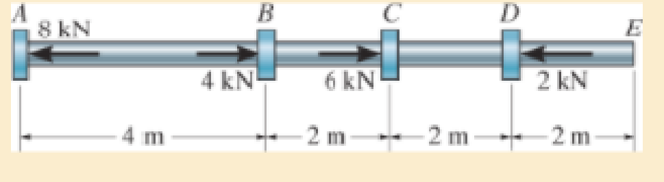
Prob. 4–5
Expert Solution & Answer
Want to see the full answer?
Check out a sample textbook solution
Students have asked these similar questions
4-9. The assembly consists of two 10-mm diameter red
brass C83400 copper rods AB and CD, a 15-mm diameter
304 stainless steel rod EF, and a rigid bar G. If P = 5 kN,
determine the horizontal displacement of end F of rod EF.
A
C
-300 mm-
B
DG
E
P
450 mm-
F
4P
The assembly below consists of a steel rod CB and an aluminium rod BA, each having a diameter of 12 mm.
If the rod is subjected to the axial loadings at A and at the coupling B, determine the displacement of the coupling B and the end A.
The unstretched length of each segment is shown below. Neglect the size of the connections at B and C, and assume that they are rigid. Est = 200 GPa, Eal = 70 GPa.
4-7. The assembly consists of two 12-mm-diameter
A992 steel rods AB and CD, a 20-mm-diameter 6061-T6
aluminum rod EF, and a rigid bar AEC. If P = 20 kN,
determine the displacement of F.
P
F
600 mm:
2P
2P
A
E
C
400 mm
B
D
Chapter 4 Solutions
Mechanics of Materials (10th Edition)
Ch. 4.2 - In each case, determine the internal normal force...Ch. 4.2 - Determine the internal normal force between...Ch. 4.2 - The post weighs 8kN/m. Determine the internal...Ch. 4.2 - The rod is subjected to an external axial force of...Ch. 4.2 - The rigid beam supports the load of 60 kN....Ch. 4.2 - The 20-mm-diameter A-36 steel rod is subjected to...Ch. 4.2 - Segments AB and CD of the assembly are solid...Ch. 4.2 - The 30-mm-diameter A992 steel rod is subjected to...Ch. 4.2 - If the 20-mm-diameter rod is made of A-36 steel...Ch. 4.2 - The 20-mm-diameter 2014-T6 aluminum rod is...
Ch. 4.2 - The 20-mm-diameter 2014-T6 aluminum rod is...Ch. 4.2 - The A992 steel rod is subjected to the loading...Ch. 4.2 - The copper shaft is subjected to the axial loads...Ch. 4.2 - The composite shaft, consisting of aluminum,...Ch. 4.2 - The composite shaft, consisting of aluminum,...Ch. 4.2 - The 2014-T6 aluminium rod has a diameter of 30 mm...Ch. 4.2 - The A-36 steel drill shaft of an oil well extends...Ch. 4.2 - The truss is made of three A-36 steel members,...Ch. 4.2 - The truss is made of three A-36 steel members,...Ch. 4.2 - The assembly consists of two 10-mm diameter red...Ch. 4.2 - The assembly consists of two 10-mm diameter red...Ch. 4.2 - The load is supported by the four 304 stainless...Ch. 4.2 - The load is supported by the four 304 stainless...Ch. 4.2 - The rigid bar is supported by the pin-connected...Ch. 4.2 - The post is made of Douglas fir and has a diameter...Ch. 4.2 - The post is made of Douglas fir and has a diameter...Ch. 4.2 - The coupling rod is subjected to a force of 5 kip....Ch. 4.2 - The pipe is stuck in the ground so that when it is...Ch. 4.2 - The is made of three pin-connected A992 steel...Ch. 4.2 - The linkage is made of three pin connected A992...Ch. 4.2 - The assembly consists of three titanium...Ch. 4.2 - The rigid beam is supported at its ends by two...Ch. 4.2 - The rigid beam is supported at its ends by two...Ch. 4.2 - The steel bar has the original dimensions shown in...Ch. 4.2 - Determine the relative displacement of one end of...Ch. 4.2 - The assembly consists of two rigid bars that are...Ch. 4.2 - The truss consists of three members, each made...Ch. 4.2 - Solve Prob. 426 when the load P acts vertically...Ch. 4.2 - The observation cage C has a weight of 250 kip and...Ch. 4.2 - The steel bar has the original dimensions shown in...Ch. 4.2 - The ball is truncated at its ends and is used to...Ch. 4.5 - The column is constructed from high-strength...Ch. 4.5 - The column is constructed from high-strength...Ch. 4.5 - The A-36 steel pipe has a 6061-T6 aluminum core....Ch. 4.5 - If column AB is made from high strength precast...Ch. 4.5 - If column AB is made from high strength precast...Ch. 4.5 - Determine the support reactions at the rigid...Ch. 4.5 - If the supports at A and C are flexible and have a...Ch. 4.5 - The load of 2000 lb is to be supported by the two...Ch. 4.5 - The load of 2000 lb is to be supported by the two...Ch. 4.5 - The A-36 steel pipe has an outer radius of 20 mm...Ch. 4.5 - The 10-mm-diameter steel bolt is surrounded by a...Ch. 4.5 - The 10-mm-diameter steel bolt is surrounded by a...Ch. 4.5 - The assembly consists of two red brass C83400...Ch. 4.5 - The rigid beam is supported by the three suspender...Ch. 4.5 - The bolt AB has a diameter of 20 mm and passes...Ch. 4.5 - If the gap between C and the rigid wall at D is...Ch. 4.5 - The support consists of a solid red brass C83400...Ch. 4.5 - If there are n fibers, each having a...Ch. 4.5 - The rigid bar is pinned at A and supported by two...Ch. 4.5 - The rigid bar is pinned at A and supported by two...Ch. 4.5 - The rigid bar is pinned at A and supported by two...Ch. 4.5 - The rigid bar is pinned at A and supported by two...Ch. 4.5 - The 2014-T6 aluminum rod AC is reinforced with the...Ch. 4.5 - The 2014-T6 aluminum rod AC is reinforced with the...Ch. 4.5 - The three suspender bars are made of A992 steel...Ch. 4.5 - The three A-36 steel wires each have a diameter of...Ch. 4.5 - The A-36 steel wires AB and AD each have a...Ch. 4.5 - The post is made from 6061-T6 aluminum and has a...Ch. 4.5 - The post is made from 6061-T6 aluminum and has a...Ch. 4.5 - The bracket is held to the wall using three A-36...Ch. 4.5 - The bracket is held to the wall using three A-36...Ch. 4.5 - If each of the posts has an unloaded length of 1 m...Ch. 4.5 - The rigid bar is supported by the two short white...Ch. 4.5 - The assembly consists of two posts AB and CD each...Ch. 4.5 - The assembly consists of two posts AB and CD each...Ch. 4.5 - The assembly consists of two posts AB and CD each...Ch. 4.5 - The wheel is subjected to a force of 18 kN from...Ch. 4.6 - The C83400-red-brass rod AB and 2014-T6- aluminum...Ch. 4.6 - The assembly has the diameters and material...Ch. 4.6 - The rod is made of A992 steel and has a diameter...Ch. 4.6 - The two cylindrical rod segments are fixed to the...Ch. 4.6 - The two cylindrical rod segments are fixed to the...Ch. 4.6 - The pipe is made of A992 steel and is connected to...Ch. 4.6 - The bronze C86100 pipe has an inner radius of 0.5...Ch. 4.6 - The 40-ft-long A-36 steel rails on a train track...Ch. 4.6 - The device is used to measure a change in...Ch. 4.6 - The bar has a cross-sectional area A, length L,...Ch. 4.6 - When the temperature is at 30C, the A-36 steel...Ch. 4.6 - When the temperature is at 30C, the A-36 steel...Ch. 4.6 - When the temperature is at 30C, the A-36 steel...Ch. 4.6 - The 50-mm-diameter cylinder is made from Am...Ch. 4.6 - The 50-mm-diameter cylinder is made from Am...Ch. 4.6 - The wires AB and AC are made of steel, and wire AD...Ch. 4.6 - The cylinder CD of the assembly is heated from T1...Ch. 4.6 - The cylinder CD of the assembly is heated from T1=...Ch. 4.6 - The metal strap has a thickness t and width w and...Ch. 4.9 - Determine the maximum normal stress developed in...Ch. 4.9 - If the allowable normal stress for the bar is...Ch. 4.9 - The steel bar has the dimensions shown. Determine...Ch. 4.9 - The A-36 steel plate has a thickness of 12 mm. If...Ch. 4.9 - Determine the maximum axial force P that can be...Ch. 4.9 - Determine the maximum normal stress developed in...Ch. 4.9 - The member is to be made from a steel plate that...Ch. 4.9 - The resulting stress distribution along section AB...Ch. 4.9 - The resulting stress distribution along section AB...Ch. 4.9 - Prob. 4.96PCh. 4.9 - The weight is suspended from steel and aluminum...Ch. 4.9 - The bar has a cross-sectional area of 0.5 in2 and...Ch. 4.9 - The distributed loading is applied to the rigid...Ch. 4.9 - The distributed loading is applied to the rigid...Ch. 4.9 - The rigid lever arm is supported by two A-36 steel...Ch. 4.9 - The rigid lever arm is supported by two A-36 steel...Ch. 4.9 - The 300-kip weight is slowly set on the top of a...Ch. 4.9 - The rigid beam is supported by three 25-mm...Ch. 4.9 - The rigid beam is supported by three 25-mm...Ch. 4.9 - The rigid beam is supported by the three posts A,...Ch. 4.9 - The rigid beam is supported by the three posts A,...Ch. 4.9 - The bar having a diameter of 2 in. is fixed...Ch. 4.9 - Determine the elongation of the bar in Prob.4108...Ch. 4.9 - The rigid beam is supported by three A-36 steel...Ch. 4 - The assembly consists of two A992 steel bolts AB...Ch. 4 - The assembly shown consists of two A992 steel...Ch. 4 - The rods each have the same 25-mm diameter and...Ch. 4 - Two A992 steel pipes, each having a...Ch. 4 - The force P is applied to the bar, which is made...Ch. 4 - The 2014-T6 aluminum rod has a diameter of 0.5 in....Ch. 4 - The 2014-T6 aluminum rod has a diameter of 0.5 in....Ch. 4 - The rigid link is supported by a pin at A and two...Ch. 4 - The joint is made from three A992 steel plates...
Knowledge Booster


Learn more about
Need a deep-dive on the concept behind this application? Look no further. Learn more about this topic, mechanical-engineering and related others by exploring similar questions and additional content below.Similar questions
- If P = 4.1 kN , determine the horizontal displacement of end F of rod EF.arrow_forward4-1. The copper shaft is subjected to the axial loads shown. Determine the displacement of end A with respect to end D. The diameters of each segment are dAB = 3 in., dBc = 2 in., and dcD = 1 in. Take Ecu = 18(10³) ksi. -50 in.- 75 in. 60 in. 6 kip A 2 kip B2 kip Prob. 4-1 C 3 kip D 1 kiparrow_forwardEach member of the truss has a cross-sectional area of 1850 mm2 and is made of A-36 steel (E=233 GPa). If P = 20 kN, determine the horizontal displacement of joint A.arrow_forward
- 4-2. The assembly consists of an A-36 steel rod CB and an a 2014-T6 aluminum rod BA, each having a diameter of 20 mm. If the rod is subjected to the axial loadings at A and at the coupling B, determine the displacement of the coupling B and the end A. Neglect the size of the connections at B and C. 80 KN B 50 kN 1m 1.5 m Prob. 4-2arrow_forwardA 4-14. The post is made of Douglas fir and has a diameter of 60 mm. If it is subjected to the load of 20 kN and the soil provides a frictional resistance that is uniformly distributed along its sides of w = 4 kN/m, determine the force F at its 20 kN bottom needed for equilibrium. Also, what is the displacement of the top of the post A with respect to its bottom B? Neglect the weight of the post. 4-19. The assembly consists of two A-36 steel rods and a rigid bar BD. Each rod has f10k unliad to thaarrow_forwardThe rigid bar AB and CD are supported by pins at A and D. the vertical rods are made of aluminum and bronze. Determine the vertical displacement of the point where the force P= 10 kips is applied. Neglect the weight of the members.arrow_forward
- *4-20. The assembly consists of three titanium (Ti-6A1-4V) rods and a rigid bar AC. The cross-sectional area of each rod is given in the figure. If a force of 60 kip horizontal displacement of point F. is applied to the ring F, determine the AF-2 in² 1 ft 60 kip F-2 ft 2 ft E E 6 ft AAB-1 in² Acp-1.5 in² 6 ftarrow_forward4-19. The assembly consists of two A-36 steel rods and a rigid bar BD. Each rod has a diameter of 0.75 in. If a force of 10 kip is applied to the bar, determine the angle of tilt of the bar. 3 ft 2 ft E D -1.25 ft- 0.75 ft 1 ft 10 kip END Thank youarrow_forward02:27 MENG360 - C... Problems (8th edition): 4.4 - 4.6 – 4.14 - 4.19 1 *4-4. The A-36 steel rod is subjected to the loading shown. If the cross-sectional area of the rod is 50 mm², determine the displacement of C. Neglect the size of the couplings at B, C, and D. 1m 1.5 m –1.25 m · ÞA 9 kN B C 4 kN D 2 kN 4-6. The bar has a cross-sectional area of 3 in?, and E = 35(10) ksi. Determine the displacement of its end A when it is subjected to the distributed loading.arrow_forward
- The truss is made of three A-36 steel members, each having a cross-sectional area of 400 mm2. Determine the horizontal displacement of the roller at C when P = 8 kN.arrow_forwardThe bronze C86100 pipe has an outer diameter of 1.5 in. and a thickness of 0.125 in. The coupling on it at C is being tightened using a wrench. If the torque developed at A is 125 lb # in., determine the magnitude F of the couple forces. The pipe is fixed supported at end B.arrow_forward4-67. The assembly consists of a 15 mm nsod 250mm o loaulabo Probs. 4-65/66 6061-T6-aluminum nas a width of 200 mm and they are not bonded together. 750 mm Aluminum- Red brass 150 mm -75 mmarrow_forward
arrow_back_ios
SEE MORE QUESTIONS
arrow_forward_ios
Recommended textbooks for you
 Elements Of ElectromagneticsMechanical EngineeringISBN:9780190698614Author:Sadiku, Matthew N. O.Publisher:Oxford University Press
 Mechanics of Materials (10th Edition)Mechanical EngineeringISBN:9780134319650Author:Russell C. HibbelerPublisher:PEARSON
 Thermodynamics: An Engineering ApproachMechanical EngineeringISBN:9781259822674Author:Yunus A. Cengel Dr., Michael A. BolesPublisher:McGraw-Hill Education
 Control Systems EngineeringMechanical EngineeringISBN:9781118170519Author:Norman S. NisePublisher:WILEY
 Mechanics of Materials (MindTap Course List)Mechanical EngineeringISBN:9781337093347Author:Barry J. Goodno, James M. GerePublisher:Cengage Learning
 Engineering Mechanics: StaticsMechanical EngineeringISBN:9781118807330Author:James L. Meriam, L. G. Kraige, J. N. BoltonPublisher:WILEY
Elements Of Electromagnetics
Mechanical Engineering
ISBN:9780190698614
Author:Sadiku, Matthew N. O.
Publisher:Oxford University Press
Mechanics of Materials (10th Edition)
Mechanical Engineering
ISBN:9780134319650
Author:Russell C. Hibbeler
Publisher:PEARSON
Thermodynamics: An Engineering Approach
Mechanical Engineering
ISBN:9781259822674
Author:Yunus A. Cengel Dr., Michael A. Boles
Publisher:McGraw-Hill Education
Control Systems Engineering
Mechanical Engineering
ISBN:9781118170519
Author:Norman S. Nise
Publisher:WILEY
Mechanics of Materials (MindTap Course List)
Mechanical Engineering
ISBN:9781337093347
Author:Barry J. Goodno, James M. Gere
Publisher:Cengage Learning
Engineering Mechanics: Statics
Mechanical Engineering
ISBN:9781118807330
Author:James L. Meriam, L. G. Kraige, J. N. Bolton
Publisher:WILEY
Mechanical Design (Machine Design) Clutches, Brakes and Flywheels Intro (S20 ME470 Class 15); Author: Professor Ted Diehl;https://www.youtube.com/watch?v=eMvbePrsT34;License: Standard Youtube License