
Videos
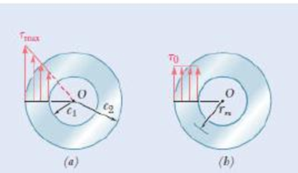
Fig. P3.29
3.29 While the exact distribution of the shearing stresses in a hollow-cylindrical shaft is as shown in Fig. P3.29a, an approximate value can be obtained for
Want to see the full answer?
Check out a sample textbook solution
Chapter 3 Solutions
Mechanics of Materials, 7th Edition


- 3.44 An aluminum tube with the hexagonal cross section shown is 2.5 ft long and has a constant wall thickness of 0.080 in. Find (a) the largest torque that the tube can carry if the shear stress is limited to 7200 psi; and (b) the angle of twist caused by this torque. Use G 4 x 10 psi for aluminum. -15 in - 0.075 in FIG. P3.44arrow_forwardA two celled tube with wall thickness 0.5 mm is subjected to a torque of 10 N.m as shown in Fig.(4). The resulting shear flows in two shells are shown below 50mm a. 9₁ +92 = 2000N/m b. 91 - 92 = 2000N/m 91 c. 291 +92 = 2000N/m d. q1 + 2q2 = 2000N/m Fig. (4) 92 50mm 50mmarrow_forward3.13 The torques T and 2T are carried by a shaft consisting of steel and aluminum segments. If the working shear stresses are 14 000 psi for steel and 7500 psi for aluminum, and the angle of rotation at the free end must not exceed 8, find the largest allowable value of T. For steel, use G = 12 x10^6 psi, and for aluminum, use G = 4 x10^6psi. T Aluminum 1.5 in.- 27/ Steel 2 in. + گری برای Happy 2 ft 3 ft as 3.14 T angle showrarrow_forward
- A ship's propeller shaft is 5 inches in diameter. The thrust load is 12,000 lb and the torque is 150,000 in - lb. Determine the resultant maximum shearing and compressive ( tensile ) stresses.arrow_forwardPin Fig. 4.21 Find the minimum size of a hole that can be punched in a 20 mm thick mild steel plate having an ultimate shear strength of 300 N/mm. The maximum permissible compressive stress in the punch material is 1200 N/mm. [Ans. 20 mm]arrow_forwardEx. 5.4 The stresses acting on an element of a loaded body are shown below. Apply Mohr's circle to determine the normal and shear stresses acting on a plane defined by 0 = 30°. Sol. YA 30° 14 MPa -28 MPaarrow_forward
- 1. A flanged bolt coupling consists of 20-mm aluminum bolts evenly spaced around a bolt circle 30 cm diameter and 12-mm steel bolts on a concentric bolt circle 20 cm in diameter. The allowable shearing stresses are 42 MPa in the aluminum and 62 MPa in the steel. What should be the minimum number of aluminum bolts if there are four steel bolts and the power applied is 760 kW at 600 rpm? Use Gal = 28 GPa and Gst = 83 GPa. 2. A torque of 1880 lb-ft is applied to the tube that has an elliptical shape with major and minor outside diameters of 6 in. and 3 in., respectively. Determine the minimum wall thickness so as not to exceed a shear stress of 8 ksi. Kindly answer please. I need ASAP thank youarrow_forwardQ4 Direct stresses of 160N/mm2 tensile and 120 N/mm2 compressive exist on two perpendicular planes at a certain point in a body. They are also accompanied by shear stresses on the planes. The greatest principal stress at the point due to these is 200 N/mm2. What must be the magnitude of the shearing stresses on the two planes? What will be the maximum shearing stress at the point?arrow_forward1. A 1.5-m long circular cross-sectioned bar with r = 1 cm is under a combination of bending moment of 70 N-m and torque of 50 N-m. Determine (a) the location of the critical point on the bar. (b) the resulting normal stress at the critical point. 6 (c) the resulting shear stress at the critical point. T ) "P (d) the principal stresses, principal direction, and maximum shear stress at the critical point. 6₁,2 (e) Draw a Mohr's circle representing the state of stress at the critical point. 1.5 m M = 70 N-m T = 50 N-marrow_forward
- Several forces (F = 200 N and P = 150 N) are applied to the pipe assembly as shown in Figure Q1(b). Knowing that the inner and outer diameters of the pipe are equal to 40 mm and 45 mm, respectively, determine: a) the principal planes and the principal stresses at point H located at the top of the outside surface of the pipe and sketch the orientation of the element, b) the maximum in-plane shearing stress at the same point and sketch the orientation of the element c) the absolute maximum shearing stress at the same pointarrow_forwardWhen a bar with the hexagonal cross section shown in Fig. (a) is subjected to a torque T, numerical analysis shows that the maximum shear stress in the bar is Tmax = 5.7T|3. Determine the percentage loss in strength that results when a circular bar of diameter dis machined into the hexagonal shape shown in Fig. (b). Location of Tmax- (a) (b) FIG. P3.53arrow_forward3. The propeller of a fishing boat is rigidly connected to a 3.8-cm. driveshaft through a O.95- cm diameter steel bolt. The bolt was designed to shear/break when the shear stress caused by hitting an underwater debris or obstruction reaches 180 MPa. Determine the contact force on the propeller blade (upon hitting a debris or obstruction) that will cause the bolt to shear/break. Assume the contact point of the debris or obstruction on the blade is 10- cm from the center of the propeller. Contact point of debris or obstruction Fc Fs- shearing force Fc- contact force T- torque Bolt 10 cm Driveshaft Fs Fs-arrow_forward
 Elements Of ElectromagneticsMechanical EngineeringISBN:9780190698614Author:Sadiku, Matthew N. O.Publisher:Oxford University Press
 Mechanics of Materials (10th Edition)Mechanical EngineeringISBN:9780134319650Author:Russell C. HibbelerPublisher:PEARSON
 Thermodynamics: An Engineering ApproachMechanical EngineeringISBN:9781259822674Author:Yunus A. Cengel Dr., Michael A. BolesPublisher:McGraw-Hill Education
 Control Systems EngineeringMechanical EngineeringISBN:9781118170519Author:Norman S. NisePublisher:WILEY
 Mechanics of Materials (MindTap Course List)Mechanical EngineeringISBN:9781337093347Author:Barry J. Goodno, James M. GerePublisher:Cengage Learning
 Engineering Mechanics: StaticsMechanical EngineeringISBN:9781118807330Author:James L. Meriam, L. G. Kraige, J. N. BoltonPublisher:WILEY