
Concept explainers
Videos
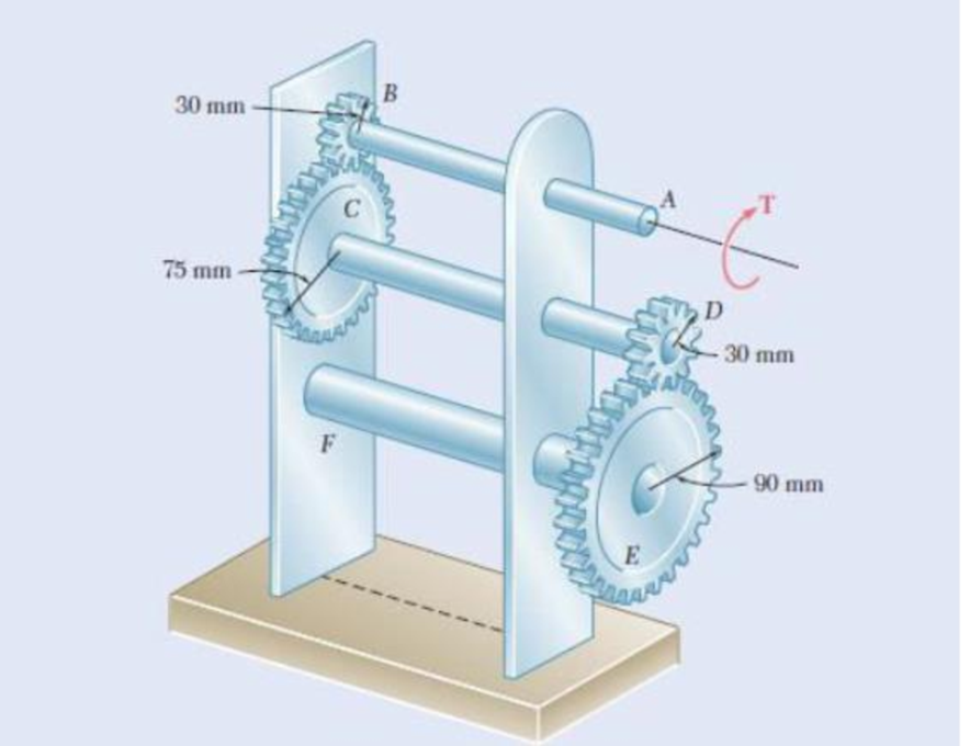
Fig. P3.27 and P3.28
3.28 A torque T = 900 N m is applied to shaft AB of the gear train shown. Knowing that the allowable shearing stress is 80 MPa, determine the required diameter of (a) shaft AB, (b) shaft CD, (c) shaft EF.
(a)
The required diameter of the shaft AB.
Answer to Problem 28P
The required diameter of the shaft AB is
Explanation of Solution
Given information:
The torque applied to the shaft AB is
The allowable shear stress is 80 MPa.
Calculation:
The torsion formula for maximum shear stress in the solid shaft AB
Here, T is the applied internal torque in the shaft AB, J is the polar moment of inertia of the shaft, and c is the radius of the shaft AB.
The polar moment of inertia for a solid shaft AB
Substitute
The torque in the shaft AB is
Substitute
Diameter of the shaft AB is twice the radius of the shaft AB.
Therefore, the required diameter of the shaft AB is
(b)
The required diameter of the shaft CD.
Answer to Problem 28P
The required diameter of the shaft CD is
Explanation of Solution
Given information:
The torque applied to the shaft AB is
The allowable shear stress is 80 MPa.
Calculation:
The torsion formula for maximum shear stress in the solid shaft CD
Here, T is the applied internal torque in the shaft CD, J is the polar moment of inertia of the shaft, and c is the radius of the shaft CD.
The polar moment of inertia for a solid shaft CD
Substitute
The torque in the shaft CD is expressed as follows:
Here,
Substitute 75 mm for
Substitute
Diameter of the shaft CD is twice the radius of the shaft CD.
Therefore, the required diameter of the shaft CD is
(c)
The required diameter of the shaft EF.
Answer to Problem 28P
The required diameter of the shaft EF is
Explanation of Solution
Given information:
The torque applied to the shaft AB is
Allowable shear stress is 80 MPa.
Calculation:
The torsion formula for maximum shear stress in the solid shaft EF
Here, T is the applied internal torque in the shaft EF, J is the polar moment of inertia of the shaft, and c is the radius of the shaft EF.
The polar moment of inertia for a solid shaft EF
Substitute
The torque in the shaft EF is expressed as follows:
Here,
Substitute 90 mm for
Substitute
Diameter of the shaft EF is twice the radius of the shaft EF.
Therefore, the required diameter of the shaft EF is
Want to see more full solutions like this?
Chapter 3 Solutions
Mechanics of Materials, 7th Edition


- PROBLEM 3.23 240 mm Two solid shafts are connected by the gears shown. A torque of magnitude T = 900 N m is applied to shaft AB. Knowing that the allowable shearing stress is 50 MPa and considering only stresses due to twisting, determine the required diameter of (a) shaft AB, (b) shaft CD. 80 mm dAR = 2c = 45.1 mm dcD = 2c = 65.0 mmarrow_forwardA solid steel shaft will not twist through more than 3 degrees in a 6-m length when subjected to a torque of 12 KN*m. The modulus of rigidity of the steel shaft is 83 GPa. Determine; a) Diarneter of the shaft. (. b) Maximum shearing stress developed in the shaft.arrow_forward3.42 The angle of rotation of end A of the gear-and-shaft system shown must not exceed 4°. Knowing that the shafts are made of a steel for which Tall = 65 MPa and G = 77.2 GPa, determine the largest torque T that can be safely applied at end A. 30 mm B Tahap 60 mm 90 mm 30 mm 0.2 m 0.4 m 0.2 m 0.1 m 0.5 marrow_forward
- 3,27 F'or the gear train shown, the diameters of the three solid shafts a dan = 20 mm dcp = 25 mm deF = 40 mm Knowing that for each shaft the allowable shearing stress is 60 MPa, determine the largest torque T that can be applied B 30 mm T 75 mm 30 mm 90 mm E Fig. P3.27arrow_forwardas shown, determine the angle of twist between (a) B and C, 3.35 The electric motor exerts a 500 N•m-torque on the aluminum shaft ABCD when it is rotating at a constant speed. Knowing that G = 27 GPa and that the torques exerted on pulleys B and C are as shown, determine the angle of twist between (a) R are 300 N. m 200 N - m 4S min 0.9 m B 44 mm 1.2 m 40 mm Fig. P3.35arrow_forward3.48 The design of the gear-and-shaft system shown requires that steel shafts of the same diameter be used for both AB and CD. It is further required that 7ma60 MPa and that the angle d, through which end D of shaft CD rotates not exceed 1.5. Knowing that G = 77.2 GPa, determine the required diamcter of the shafts. 40 mm 1000 N m 100 mm 400 mm 600 mm Fig. P3.48arrow_forward
- 3.36 The torques shown are exerted on pulleys B, C, and D. Knowing that the entire shaft is made of aluminum (G = 27 GPa), deter- mine the angle of twist between (a) C and B, (b) D and B. 30 mm 30 mm 400 N- m GG 36 mm 900 N- m 36 mm 500 N. m B "0.6 m E. 0.5 m D m 0.5 Fig. P3.36arrow_forward3.23 Under normal operating conditions a motor exerts a torque of magnitude T: at F. The shafts are made of a steel for which the allowable shearing stress is 82 MPa and have diameters dcDE = 24 mm and dran = 20 mm. Knowing that rp = 165 mm and rg = 114 mm, determine the largest allowable value of Tr. F. C T; B TEV E Fig. P3.23arrow_forwardFig. P3.1 18 mm 3.1 Determine the torque T that causes a maximum shearing stress of 70 MPa in the steel cylindrical shaft shown.arrow_forward
- 3.1 (a) Determine the maximum shearing stress caused by a 4.6-kN - m torque T in the 76-mm-diameter solid aluminum shaft shown. (b) Solve part a, assuming that the solid shaft has been replaced by a hollow shaft of the same outer diameter and of 24-mm inner diameter.arrow_forwardPROBLEM 3.52 A 4 kNm torque T is applied at end A of the composite shaft shown. Knowing that the shear modulus is 77 GPa for the steel and 27 GPa for the aluminium, determine (a) the maximum shear stress in the steel core, (b) the maximum shear stress in the aluminium jacket, and (c) the angle of twist at A. [Ans. (a) 73.6 MPa (b) 34.4 MPa (c) 5.07°] 72 mm 54 mm 2.5 m Steel core Aluminium jackeť Fig. P3.52 and P3.53 22:37 e dx D 14/04/2022 BANG & OLUFSEN 40 delete home end pg up pg dn num backspace lock W ERT U %23 home og up 4.arrow_forwardPROBLEM 3.52 A 4 kNm torque T is applied at end A of the composite shaft shown. Knowing that the shear modulus is 77 GPa for the steel and 27 GPa for the aluminium, determine (a) the maximum shear stress in the steel core, (b) the maximum shear stress in the aluminium jacket, and (c) the angle of twist at A. [Ans. (a) 73.6 MPa (b) 34.4 MPa (c) 5.07°] Hint: angle of twist at 72 mm end A is same for core and jacket 54 mm A 2.5 m Steel core Aluminium jacket Fig. P3.52 and P3.53 22:35 BANG & OLUFSEN delete home end og up pg dn num backspace 4 lock Q WE T U 080 home pg uparrow_forward
 Elements Of ElectromagneticsMechanical EngineeringISBN:9780190698614Author:Sadiku, Matthew N. O.Publisher:Oxford University Press
 Mechanics of Materials (10th Edition)Mechanical EngineeringISBN:9780134319650Author:Russell C. HibbelerPublisher:PEARSON
 Thermodynamics: An Engineering ApproachMechanical EngineeringISBN:9781259822674Author:Yunus A. Cengel Dr., Michael A. BolesPublisher:McGraw-Hill Education
 Control Systems EngineeringMechanical EngineeringISBN:9781118170519Author:Norman S. NisePublisher:WILEY
 Mechanics of Materials (MindTap Course List)Mechanical EngineeringISBN:9781337093347Author:Barry J. Goodno, James M. GerePublisher:Cengage Learning
 Engineering Mechanics: StaticsMechanical EngineeringISBN:9781118807330Author:James L. Meriam, L. G. Kraige, J. N. BoltonPublisher:WILEY