
Shigley's Mechanical Engineering Design (McGraw-Hill Series in Mechanical Engineering)
10th Edition
ISBN: 9780073398204
Author: Richard G Budynas, Keith J Nisbett
Publisher: McGraw-Hill Education
expand_more
expand_more
format_list_bulleted
Videos
Textbook Question
Chapter 3, Problem 49P
The beam shown is loaded in the xy and xz planes.
(a) Find the y- and z-components of the reactions at the supports.
(b) Plot the shear-force and bending-moment diagrams for the xy and xz planes. Label the diagrams properly and provide the values at key points.
(c) Determine the net shear-force and bending-moment at the key points of part (b).
(d) Determine the maximum tensile bending stress. For Prob. 3–48, use the cross section given in Prob. 3–34, part (a). For Prob. 3–49, use the cross section given in Prob. 3–39, part (b).
Problem 3–48
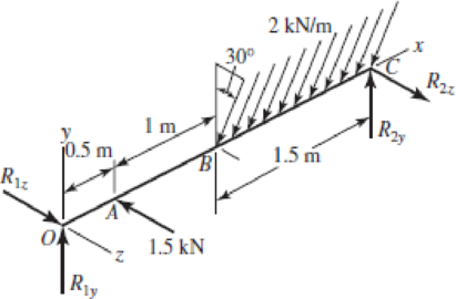
Problem 3–49
Expert Solution & Answer
Want to see the full answer?
Check out a sample textbook solution
Students have asked these similar questions
Your answer is partially correct.
For the simply supported beam subjected to the loading shown, derive equations for the shear force V and the bending moment M
for any location in the beam. (Place the origin at point A.) Let a=2.50 m, b=4.25 m, Pg= 45kN, and Pc = 90kN. Construct the shear-
force and bending-moment diagrams on paper and use the results to answer the questions in the subsequent parts of this GO
exercise.
Answers:
Ay=
a
74.189
B
Calculate the reaction forces Ay and Dy acting on the beam. Positive values for the reactions are indicated by the directions of the
red arrows shown on the free-body diagram below. (Note: Since Ax = 0, it has been omitted from the free-body diagram.)
Dy= i 59.21
B
a
PB
a
Pc
KN
Pc
b
KN
D
b
D
P
x
(a) derive equations for the shear force V and the bending momentM for any location in the beam. (Place the origin at point A.)(b) use the derived functions to plot the shear-force and bendingmomentdiagrams for the beam.(c) specify the values for key points on the diagrams.
2. The simply supported beam is loaded as shown in Figure 2. Neglecting
the weight of the beam;
(a) Derive the shear force and bending moment equations.
(b) Draw and label the shear force and bending moment diagrams.
Chapter 3 Solutions
Shigley's Mechanical Engineering Design (McGraw-Hill Series in Mechanical Engineering)
Ch. 3 - 31 to 34 Sketch a free-body diagram of each...Ch. 3 - 31 to 34 Sketch a free-body diagram of each...Ch. 3 - Sketch a free-body diagram of each element in the...Ch. 3 - 3-1 to 3-4 Sketch a free-body diagram of each...Ch. 3 - 35 to 38 For the beam shown, find the reactions at...Ch. 3 - 35 to 38 For the beam shown, find the reactions at...Ch. 3 - 35 to 38 For the beam shown, find the reactions at...Ch. 3 - For the beam shown, find the reactions at the...Ch. 3 - For the beam shown, find the reactions at the...Ch. 3 - Repeat Prob. 36 using singularity functions...
Ch. 3 - Repeat Prob. 37 using singularity functions...Ch. 3 - Repeat Prob. 38 using singularity functions...Ch. 3 - For a beam from Table A9, as specified by your...Ch. 3 - A beam carrying a uniform load is simply supported...Ch. 3 - For each of the plane stress states listed below,...Ch. 3 - Repeat Prob. 315 for: (a)x = 28 MPa, y = 7 MPa, xy...Ch. 3 - Repeat Prob. 315 for: a) x = 12 kpsi, y = 6 kpsi,...Ch. 3 - For each of the stress states listed below, find...Ch. 3 - Repeat Prob. 318 for: (a)x = 10 kpsi, y = 4 kpsi...Ch. 3 - The state of stress at a point is x = 6, y = 18, z...Ch. 3 - The state of stress at a point is x = 6, y = 18, z...Ch. 3 - Repeat Prob. 320 with x = 10, y = 40, z = 40, xy =...Ch. 3 - A 34-in-diameter steel tension rod is 5 ft long...Ch. 3 - Repeat Prob. 323 except change the rod to aluminum...Ch. 3 - A 30-mm-diameter copper rod is 1 m long with a...Ch. 3 - A diagonal aluminum alloy tension rod of diameter...Ch. 3 - Repeat Prob. 326 with d = 16 mm, l = 3 m, and...Ch. 3 - Repeat Prob. 326 with d = 58 in, l = 10 ft, and...Ch. 3 - Electrical strain gauges were applied to a notched...Ch. 3 - Repeat Prob. 329 for a material of aluminum. 3-29...Ch. 3 - The Roman method for addressing uncertainty in...Ch. 3 - Using our experience with concentrated loading on...Ch. 3 - The Chicago North Shore Milwaukee Railroad was an...Ch. 3 - For each section illustrated, find the second...Ch. 3 - 3-35 to 3-38 For the beam illustrated in the...Ch. 3 - 3-35 to 3-38 For the beam illustrated in the...Ch. 3 - 3-35 to 3-38 For the beam illustrated in the...Ch. 3 - 3-35 to 3-38 For the beam illustrated in the...Ch. 3 - The figure illustrates a number of beam sections....Ch. 3 - A pin in a knuckle joint canning a tensile load F...Ch. 3 - Repeat Prob. 3-40 for a = 6 mm, b = 18 mm. d = 12...Ch. 3 - For the knuckle joint described in Prob. 3-40,...Ch. 3 - The figure illustrates a pin tightly fitted into a...Ch. 3 - For the beam shown, determine (a) the maximum...Ch. 3 - A cantilever beam with a 1-in-diameter round cross...Ch. 3 - Consider a simply supported beam of rectangular...Ch. 3 - In Prob. 346, h 0 as x 0, which cannot occur. If...Ch. 3 - 348 and 349 The beam shown is loaded in the xy and...Ch. 3 - The beam shown is loaded in the xy and xz planes....Ch. 3 - Two steel thin-wall tubes in torsion of equal...Ch. 3 - Consider a 1-in-square steel thin-walled tube...Ch. 3 - The thin-walled open cross-section shown is...Ch. 3 - 3-53 to 3-55 Using the results from Prob. 3-52,...Ch. 3 - 3-53 to 3-55 Using the results from Prob. 3-52,...Ch. 3 - 3-53 to 3-55 Using the results from Prob. 3-52,...Ch. 3 - Two 300-mm-long rectangular steel strips are...Ch. 3 - Using a maximum allowable shear stress of 70 Mpa,...Ch. 3 - Repeat Prob. 357 with an allowable shear stress of...Ch. 3 - Using an allowable shear stress of 50 MPa,...Ch. 3 - A 20-mm-diameter steel bar is to be used as a...Ch. 3 - A 2-ft-long steel bar with a 34-in diameter is to...Ch. 3 - A 40-mm-diameter solid steel shaft, used as a...Ch. 3 - Generalize Prob. 3-62 for a solid shaft of...Ch. 3 - A hollow steel shaft is to transmit 4200 N m of...Ch. 3 - The figure shows an endless-bell conveyor drive...Ch. 3 - The conveyer drive roll in the figure for Prob....Ch. 3 - Consider two shafts in torsion, each of the same...Ch. 3 - 3-68 to 3-71 A countershaft two V-belt pulleys is...Ch. 3 - 3-68 to 3-71 A countershaft two V-belt pulleys is...Ch. 3 - 3-68 to 3-71 A countershaft two V-belt pulleys is...Ch. 3 - A countershaft carrying two V-belt pulleys is...Ch. 3 - A gear reduction unit uses the countershaft shown...Ch. 3 - Prob. 73PCh. 3 - Prob. 74PCh. 3 - Prob. 75PCh. 3 - Prob. 76PCh. 3 - Prob. 77PCh. 3 - Prob. 78PCh. 3 - Prob. 79PCh. 3 - The cantilevered bar in the figure is made from a...Ch. 3 - Repeat Prob. 3-80 with Fx = 0, Fy = 175 lbf, and...Ch. 3 - Repeat Prob. 3-80 with Fx = 75 lbf, Fy= 200 lbf,...Ch. 3 - For the handle in Prob. 3-80, one potential...Ch. 3 - The cantilevered bar in the figure is made from a...Ch. 3 - Repeat Prob. 3-84 with Fx = 300 lbf, Fy = 250 lbf,...Ch. 3 - Repeat Prob. 3-84 with Fx = 300 lbf, Fy = 250 lbf,...Ch. 3 - Repeat Prob. 3-84 for a brittle material,...Ch. 3 - Repeat Prob. 3-84 with Fx = 300 lbf, Fy = 250 lbf,...Ch. 3 - Repeat Prob. 3-84 with Fx = 300 lbf, Fy = 250 lbf,...Ch. 3 - The figure shows a simple model of the loading of...Ch. 3 - Develop the formulas for the maximum radial and...Ch. 3 - Repeat Prob. 391 where the cylinder is subject to...Ch. 3 - Develop the equations for the principal stresses...Ch. 3 - 3-94 to 3-96 A pressure cylinder has an outer...Ch. 3 - 3-94 to 3-96 A pressure cylinder has an outer...Ch. 3 - 3-94 to 3-96A pressure cylinder has an outer...Ch. 3 - 3-97 to 3-99 A pressure cylinder has an outer...Ch. 3 - 3-97 to 3-99 A pressure cylinder has an outer...Ch. 3 - 3-97 to 3-99 A pressure cylinder has an outer...Ch. 3 - An AISI 1040 cold-drawn steel tube has an OD = 50...Ch. 3 - Repeat Prob. 3-100 with an OD of 2 in and wall...Ch. 3 - Prob. 102PCh. 3 - Prob. 103PCh. 3 - A thin-walled cylindrical Steel water storage tank...Ch. 3 - Repeat Prob. 3-104 with the tank being pressurized...Ch. 3 - Find the maximum shear stress in a 512-in-diameter...Ch. 3 - The maximum recommended speed for a...Ch. 3 - An abrasive cutoff wheel has a diameter of 5 in,...Ch. 3 - A rotary lawnmower blade rotates at 3500 rev/min....Ch. 3 - 3110 to 3115 The table lists the maximum and...Ch. 3 - Prob. 111PCh. 3 - Prob. 112PCh. 3 - 3110 to 3115 The table lists the maximum and...Ch. 3 - Prob. 114PCh. 3 - Prob. 115PCh. 3 - 3116 to 3119 The table gives data concerning the...Ch. 3 - Prob. 117PCh. 3 - Prob. 118PCh. 3 - 3116 to 3119 The table gives data concerning the...Ch. 3 - A utility hook was formed from a round rod of...Ch. 3 - A utility hook was formed from a round rod of...Ch. 3 - The steel eyebolt shown in the figure is loaded...Ch. 3 - For Prob. 3122 estimate the stresses at the inner...Ch. 3 - Repeat Prob. 3122 with d = 14 in, Ri = 12 in, and...Ch. 3 - Repeat Prob. 3123 with d = 14 in, Ri = 12 in, and...Ch. 3 - Shown in the figure is a 12-gauge (0.1094-in) by...Ch. 3 - Repeat Prob. 3126 with a 10-gauge (0.1406-in)...Ch. 3 - Prob. 128PCh. 3 - The cast-iron bell-crank lever depicted in the...Ch. 3 - Prob. 130PCh. 3 - Prob. 131PCh. 3 - A cast-steel C frame as shown in the figure has a...Ch. 3 - Two carbon steel balls, each 30 mm in diameter,...Ch. 3 - A carbon steel ball with 25-mm diameter is pressed...Ch. 3 - Repeat Prob. 3134 but determine the maximum shear...Ch. 3 - A carbon steel ball with a 30-mm diameter is...Ch. 3 - An AISI 1018 steel ball with 1-in diameter is used...Ch. 3 - An aluminum alloy cylindrical roller with diameter...Ch. 3 - A pair of mating steel spur gears with a 0.75-in...Ch. 3 - 3140 to 3142 A wheel of diameter d and width w...Ch. 3 - 3140 to 3142 A wheel of diameter d and width w...Ch. 3 - 3140 to 3142 A wheel of diameter d and width w...
Knowledge Booster


Learn more about
Need a deep-dive on the concept behind this application? Look no further. Learn more about this topic, mechanical-engineering and related others by exploring similar questions and additional content below.Similar questions
- A seesaw weighing 3 lb/ft of length is occupied by two children, each weighing 90 lb (see figure). The center of gravity of each child is 8 ft from the fulcrum. The board is 19 ft long, 8 in. wide, and 1.5 in. thick. What is the maximum bending stress in the board?arrow_forward-15 A composite beam is constructed froma wood beam (3 in. x 6 in.) and a steel plate (3 in, wide). The wood and the steel are securely fastened to act as a single beam. The beam is subjected to a positive bending moment M. = 75 kip-in. Calculate the required thickness of the steel plate based on the following limit states: Allowable compressive stress in the wood = 2 ksi Allowable tensile stress in the wood = 2 ksi Allowable tensile stress in the steel plate = 16 ksi Assume that Ew= 1,500 ksi and es= 30,000 ksi.arrow_forwardA beam of rectangular cross section (width/) and height supports a uniformly distributed load along its entire length L. The allowable stresses in bending and shear are and TaUow, respectively. If the beam is simply supported, what is the span length Lübelow which the shear stress governs the allowable load and above which the bending stress governs? If the beam is supported as a cantilever, what is the length L() below which the shear stress governs the allowable load and above which the bending stress governs?arrow_forward
- SOLVE STEP BY STEP IN DIGITAL FORMAT Calculate all reactions, draw shear and moment diagramsarrow_forwardFor the simply supported beam subjected to the loading shown, derive equations for the shear force V and the bending moment M for any location in the beam. (Place the origin at point A.) Let a-3.25 m, b=4.75 m, Pg = 35kN, and Pc = 80kN. Construct the shear- force and bending-moment diagrams on paper and use the results to answer the questions in the subsequent parts of this GO exercise. Answers: Ay= Dy = a M. B a PB Calculate the reaction forces Ay and Dy acting on the beam. Positive values for the reactions are indicated by the directions of the red arrows shown on the free-body diagram below. (Note: Since Ax = 0, it has been omitted from the free-body diagram.) PB Pc a Pc kN b KN D b D X D Xarrow_forwardFor the cantilever beam shown in the figure below, invoke the equilibrium of cut free-body sections of the beam to (a) write equations for the shear force and bending moment distributions as functions of x. Include a free-body diagram of each cut section and force and moment balance calculations. Examine the shear force and bending moment formulas and deduce the sign of the deformation within each inter- val. Include a sketch of a deformed material element that illustrates the shear and bending deformation within the interval. (b) Find the shear force of the largest magnitude in the beam and state where it occurs within the beam. (c) Find the bending moment of the largest magnitude in the beam and state where it occurs within the beam. 200 N/m 0.6 m- X 600 N 0.2 m 0.2 marrow_forward
- The beam shown in Figure 2 is loaded in the xy and xz planes.(a) Find the y and z components of the reactions at the supports.(b) Plot the shear and bending moment diagrams.arrow_forward2. For the structural beam loaded and supported as shown in Figure 2, (a) Draw a free body diagram and find the support reaction forces/moments. (b) Determine the shear force values at the supports and other relevant transition points. Using these, draw the Shear Force Diagram (SFD). (c) Determine the bending moment values at the supports and other relevant transition points and draw the bending moment diagram (BMD). (d) Write the mathematical expressions for shear force and bending moment at a section X-X between the points A and B, which is at a distance x from support A. Find the distance from support A to the position of maximum bending moment and determine the value of Mmax. (e) 2 kN/m 10 kN A C D 5 m 3 m 2 m Figure 2arrow_forwardFor the simply supported beam subjected to the loading shown, derive equations for the shear force V and the bending moment M for any location in the beam. (Place the origin at point A.) Let a=4.00 m, b=5.25 m, c= 2.75 m, P = 36kN and M = 195kN-m. Construct the shear-force and bending-moment diagrams on paper and use the results to answer the questions in the subsequent parts of this GO exercise. A Answers: Ay= Cy= b Calculate the reaction forces Ay and Cy acting on the beam. Positive values for the reactions are indicated by the directions of the red arrows shown on the free-body diagram below. (Note: Since Ax = 0, it has been omitted from the free-body diagram.) i i a M a B M B b kN 2 C KN C Cy C P с X Parrow_forward
- Draw the free-body diagram for the portion of machine structure shown in Figure 1. Determinethe reactions at the supports and draw the complete shear-force and bending-moment diagramsarrow_forwardThe figure shows a cantilevered beam, subjected to a uniformly distributed (rectangular) 40 N/m force along the section DE, a 50 N point force at point C, and a 200 Nm couple moment. a. Write the shear-force and bending-moment equations as a function of distance, x, measured from the leftmost point, A, for the entire beam. b. Using your shear-force and bending-moment equations, calculate the shear force and bending moment at x = 2 m and x = 5 m. 200 N·m A 2.5 m 50 N CV D 1 m 40 N/m ↓↓↓ 2.5 m E B 2 marrow_forwardA solid cantilevered aluminum alloy rod, 10-mm in diameter, supports a Parol (Christmas Lantern). The hanging Parol subjects the rod to a bending moment of 10.2 Nm along the x-axis, as well as Torque (T) at its fixed end (Section B). If the yield strength oYield in tension of the aluminum alloy is 103.9 MPa at point n of Section B, what is the maximum torque the rod can carry under the maximum distortion-energy theory (MDET)? L aluminum rod Figure 1A Y B cross-section of the rod Figure 1B Image is from Parol clipart 2 Clipart Stationarrow_forward
arrow_back_ios
SEE MORE QUESTIONS
arrow_forward_ios
Recommended textbooks for you
 Mechanics of Materials (MindTap Course List)Mechanical EngineeringISBN:9781337093347Author:Barry J. Goodno, James M. GerePublisher:Cengage Learning
Mechanics of Materials (MindTap Course List)
Mechanical Engineering
ISBN:9781337093347
Author:Barry J. Goodno, James M. Gere
Publisher:Cengage Learning
Mechanics of Materials Lecture: Beam Design; Author: UWMC Engineering;https://www.youtube.com/watch?v=-wVs5pvQPm4;License: Standard Youtube License