
Shigley's Mechanical Engineering Design (McGraw-Hill Series in Mechanical Engineering)
10th Edition
ISBN: 9780073398204
Author: Richard G Budynas, Keith J Nisbett
Publisher: McGraw-Hill Education
expand_more
expand_more
format_list_bulleted
Concept explainers
Videos
Textbook Question
Chapter 3, Problem 33P
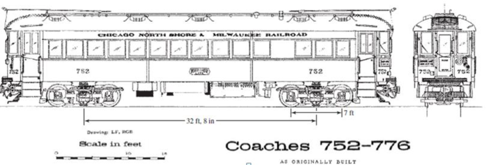
The Chicago North Shore & Milwaukee Railroad was an electric railway running between the cities in its corporate title. It had passenger cars as shown in the figure, which weighed 104.4 kip, had 32-ft. 8-in truck centers. 7-ft-wheelbase trucks, and a coupled length of 55 ft,
- (a) What was the largest bending moment in the bridge?
- (b) Where on the bridge was the moment located?
- (c) What was the position of the car on the bridge?
- (d) Under which axle is the bending moment?
Expert Solution & Answer
Want to see the full answer?
Check out a sample textbook solution
Students have asked these similar questions
For the overhanging truss shown in figure below, compute the member forces in BC, CE and DE.
5kN
3m
IB
2m
2m
5kN
10KN
ANS: BC =
kN, CE =
kN, DE =
kN (whole number)
Which of the following is/are tensile force(s)? (BC, CE, DE)
Question 5
Find the supportive force system for the cantilever beam shown pinned at C. Given data: Point load,
Not yet answered
P=380 N and distributed load, w=80 N/m.
Marked out of 5.00
on
7 m
2 m
A
5 m-
5 m-
Supportive force system
Ax=
Ay=
Сх-
N
Су-
By=
N
After an unfortunate accident occurred at a local warehouse,
you were contracted to determine the cause. A jib crane
collapsed and injured a worker. An image of this type of
crane is shown in the figure.
The horizontal steel beam had a mass of 86.80 kg per meter
of length, and the tension in the cable was T = 12170 N. The
crane was rated for a maximum load of 500 kg. The
acceleration due to gravity is g = 9.810 m/s².
If d = 6.160 m, s = 0.450 m, x = 1.500 m, and
h = 1.980 m, what was the magnitude of W₁ (the load on the
crane) before the collapse?
What was the magnitude of force Fp at the attachment
point P?
WL =
Fp =
P
0
W₁
N
N
Chapter 3 Solutions
Shigley's Mechanical Engineering Design (McGraw-Hill Series in Mechanical Engineering)
Ch. 3 - 31 to 34 Sketch a free-body diagram of each...Ch. 3 - 31 to 34 Sketch a free-body diagram of each...Ch. 3 - Sketch a free-body diagram of each element in the...Ch. 3 - 3-1 to 3-4 Sketch a free-body diagram of each...Ch. 3 - 35 to 38 For the beam shown, find the reactions at...Ch. 3 - 35 to 38 For the beam shown, find the reactions at...Ch. 3 - 35 to 38 For the beam shown, find the reactions at...Ch. 3 - For the beam shown, find the reactions at the...Ch. 3 - For the beam shown, find the reactions at the...Ch. 3 - Repeat Prob. 36 using singularity functions...
Ch. 3 - Repeat Prob. 37 using singularity functions...Ch. 3 - Repeat Prob. 38 using singularity functions...Ch. 3 - For a beam from Table A9, as specified by your...Ch. 3 - A beam carrying a uniform load is simply supported...Ch. 3 - For each of the plane stress states listed below,...Ch. 3 - Repeat Prob. 315 for: (a)x = 28 MPa, y = 7 MPa, xy...Ch. 3 - Repeat Prob. 315 for: a) x = 12 kpsi, y = 6 kpsi,...Ch. 3 - For each of the stress states listed below, find...Ch. 3 - Repeat Prob. 318 for: (a)x = 10 kpsi, y = 4 kpsi...Ch. 3 - The state of stress at a point is x = 6, y = 18, z...Ch. 3 - The state of stress at a point is x = 6, y = 18, z...Ch. 3 - Repeat Prob. 320 with x = 10, y = 40, z = 40, xy =...Ch. 3 - A 34-in-diameter steel tension rod is 5 ft long...Ch. 3 - Repeat Prob. 323 except change the rod to aluminum...Ch. 3 - A 30-mm-diameter copper rod is 1 m long with a...Ch. 3 - A diagonal aluminum alloy tension rod of diameter...Ch. 3 - Repeat Prob. 326 with d = 16 mm, l = 3 m, and...Ch. 3 - Repeat Prob. 326 with d = 58 in, l = 10 ft, and...Ch. 3 - Electrical strain gauges were applied to a notched...Ch. 3 - Repeat Prob. 329 for a material of aluminum. 3-29...Ch. 3 - The Roman method for addressing uncertainty in...Ch. 3 - Using our experience with concentrated loading on...Ch. 3 - The Chicago North Shore Milwaukee Railroad was an...Ch. 3 - For each section illustrated, find the second...Ch. 3 - 3-35 to 3-38 For the beam illustrated in the...Ch. 3 - 3-35 to 3-38 For the beam illustrated in the...Ch. 3 - 3-35 to 3-38 For the beam illustrated in the...Ch. 3 - 3-35 to 3-38 For the beam illustrated in the...Ch. 3 - The figure illustrates a number of beam sections....Ch. 3 - A pin in a knuckle joint canning a tensile load F...Ch. 3 - Repeat Prob. 3-40 for a = 6 mm, b = 18 mm. d = 12...Ch. 3 - For the knuckle joint described in Prob. 3-40,...Ch. 3 - The figure illustrates a pin tightly fitted into a...Ch. 3 - For the beam shown, determine (a) the maximum...Ch. 3 - A cantilever beam with a 1-in-diameter round cross...Ch. 3 - Consider a simply supported beam of rectangular...Ch. 3 - In Prob. 346, h 0 as x 0, which cannot occur. If...Ch. 3 - 348 and 349 The beam shown is loaded in the xy and...Ch. 3 - The beam shown is loaded in the xy and xz planes....Ch. 3 - Two steel thin-wall tubes in torsion of equal...Ch. 3 - Consider a 1-in-square steel thin-walled tube...Ch. 3 - The thin-walled open cross-section shown is...Ch. 3 - 3-53 to 3-55 Using the results from Prob. 3-52,...Ch. 3 - 3-53 to 3-55 Using the results from Prob. 3-52,...Ch. 3 - 3-53 to 3-55 Using the results from Prob. 3-52,...Ch. 3 - Two 300-mm-long rectangular steel strips are...Ch. 3 - Using a maximum allowable shear stress of 70 Mpa,...Ch. 3 - Repeat Prob. 357 with an allowable shear stress of...Ch. 3 - Using an allowable shear stress of 50 MPa,...Ch. 3 - A 20-mm-diameter steel bar is to be used as a...Ch. 3 - A 2-ft-long steel bar with a 34-in diameter is to...Ch. 3 - A 40-mm-diameter solid steel shaft, used as a...Ch. 3 - Generalize Prob. 3-62 for a solid shaft of...Ch. 3 - A hollow steel shaft is to transmit 4200 N m of...Ch. 3 - The figure shows an endless-bell conveyor drive...Ch. 3 - The conveyer drive roll in the figure for Prob....Ch. 3 - Consider two shafts in torsion, each of the same...Ch. 3 - 3-68 to 3-71 A countershaft two V-belt pulleys is...Ch. 3 - 3-68 to 3-71 A countershaft two V-belt pulleys is...Ch. 3 - 3-68 to 3-71 A countershaft two V-belt pulleys is...Ch. 3 - A countershaft carrying two V-belt pulleys is...Ch. 3 - A gear reduction unit uses the countershaft shown...Ch. 3 - Prob. 73PCh. 3 - Prob. 74PCh. 3 - Prob. 75PCh. 3 - Prob. 76PCh. 3 - Prob. 77PCh. 3 - Prob. 78PCh. 3 - Prob. 79PCh. 3 - The cantilevered bar in the figure is made from a...Ch. 3 - Repeat Prob. 3-80 with Fx = 0, Fy = 175 lbf, and...Ch. 3 - Repeat Prob. 3-80 with Fx = 75 lbf, Fy= 200 lbf,...Ch. 3 - For the handle in Prob. 3-80, one potential...Ch. 3 - The cantilevered bar in the figure is made from a...Ch. 3 - Repeat Prob. 3-84 with Fx = 300 lbf, Fy = 250 lbf,...Ch. 3 - Repeat Prob. 3-84 with Fx = 300 lbf, Fy = 250 lbf,...Ch. 3 - Repeat Prob. 3-84 for a brittle material,...Ch. 3 - Repeat Prob. 3-84 with Fx = 300 lbf, Fy = 250 lbf,...Ch. 3 - Repeat Prob. 3-84 with Fx = 300 lbf, Fy = 250 lbf,...Ch. 3 - The figure shows a simple model of the loading of...Ch. 3 - Develop the formulas for the maximum radial and...Ch. 3 - Repeat Prob. 391 where the cylinder is subject to...Ch. 3 - Develop the equations for the principal stresses...Ch. 3 - 3-94 to 3-96 A pressure cylinder has an outer...Ch. 3 - 3-94 to 3-96 A pressure cylinder has an outer...Ch. 3 - 3-94 to 3-96A pressure cylinder has an outer...Ch. 3 - 3-97 to 3-99 A pressure cylinder has an outer...Ch. 3 - 3-97 to 3-99 A pressure cylinder has an outer...Ch. 3 - 3-97 to 3-99 A pressure cylinder has an outer...Ch. 3 - An AISI 1040 cold-drawn steel tube has an OD = 50...Ch. 3 - Repeat Prob. 3-100 with an OD of 2 in and wall...Ch. 3 - Prob. 102PCh. 3 - Prob. 103PCh. 3 - A thin-walled cylindrical Steel water storage tank...Ch. 3 - Repeat Prob. 3-104 with the tank being pressurized...Ch. 3 - Find the maximum shear stress in a 512-in-diameter...Ch. 3 - The maximum recommended speed for a...Ch. 3 - An abrasive cutoff wheel has a diameter of 5 in,...Ch. 3 - A rotary lawnmower blade rotates at 3500 rev/min....Ch. 3 - 3110 to 3115 The table lists the maximum and...Ch. 3 - Prob. 111PCh. 3 - Prob. 112PCh. 3 - 3110 to 3115 The table lists the maximum and...Ch. 3 - Prob. 114PCh. 3 - Prob. 115PCh. 3 - 3116 to 3119 The table gives data concerning the...Ch. 3 - Prob. 117PCh. 3 - Prob. 118PCh. 3 - 3116 to 3119 The table gives data concerning the...Ch. 3 - A utility hook was formed from a round rod of...Ch. 3 - A utility hook was formed from a round rod of...Ch. 3 - The steel eyebolt shown in the figure is loaded...Ch. 3 - For Prob. 3122 estimate the stresses at the inner...Ch. 3 - Repeat Prob. 3122 with d = 14 in, Ri = 12 in, and...Ch. 3 - Repeat Prob. 3123 with d = 14 in, Ri = 12 in, and...Ch. 3 - Shown in the figure is a 12-gauge (0.1094-in) by...Ch. 3 - Repeat Prob. 3126 with a 10-gauge (0.1406-in)...Ch. 3 - Prob. 128PCh. 3 - The cast-iron bell-crank lever depicted in the...Ch. 3 - Prob. 130PCh. 3 - Prob. 131PCh. 3 - A cast-steel C frame as shown in the figure has a...Ch. 3 - Two carbon steel balls, each 30 mm in diameter,...Ch. 3 - A carbon steel ball with 25-mm diameter is pressed...Ch. 3 - Repeat Prob. 3134 but determine the maximum shear...Ch. 3 - A carbon steel ball with a 30-mm diameter is...Ch. 3 - An AISI 1018 steel ball with 1-in diameter is used...Ch. 3 - An aluminum alloy cylindrical roller with diameter...Ch. 3 - A pair of mating steel spur gears with a 0.75-in...Ch. 3 - 3140 to 3142 A wheel of diameter d and width w...Ch. 3 - 3140 to 3142 A wheel of diameter d and width w...Ch. 3 - 3140 to 3142 A wheel of diameter d and width w...
Knowledge Booster


Learn more about
Need a deep-dive on the concept behind this application? Look no further. Learn more about this topic, mechanical-engineering and related others by exploring similar questions and additional content below.Similar questions
- For the truss below, label members AB, CF, and EF as either "T" (tension), "C" (compression), or "zero-force." If there are none of a particular type, place it next to "none." 6ft (TYP) T *6* 2 T C 2k Zero-force 3k NONE: 12.54arrow_forwardwe want to build a single-rail overhead crane in the workshop.when the load reaches the extreme point, it is 1800 mm away. the rail-shaped profile iron of the crane is connected from point B to point A by rope.the tensile stress of the rope is = 600 mpa. and the cross-sectional area is a=802 mm.according to other dimensions given (a=850mm b=1500 mm), this vince can hang No more than how many kg of load.(G=?)arrow_forwardA new art exhibit featuring mobile works is going up in the Norwalk, CA area. One art work is shown in the figure below. A 105 N uniform beam is pinned to the ground by a pivot. The beam is supported by a cable (attached 3/5 from the bottom of the beam) to allow for each of the shoes to hang freely. Each individual shoe has a weight of 7.5 N. 10 WALL FLOR (a) ( If one shoe is attached 1/7 of the way up the beam and another shoe is attached 5/8 of the way up the beam, with e, = 70.1° and e, 30.1°, what is the tension in the cable, in newtons? %3! %3D (b) What is the x-component of the force, in newtons, that the pivot exerts on the bottom of the beam? (c) O What is the y-component of the force, in newtons, that the pivot exerts on the bottom of the beam?arrow_forward
- A board of mass mand length l is attached to a wall and a rope that makes an angle of theta, as shown. A block of mass M hangs from the right end of the board. Suppose m = 2.0kg, L = .60m, M = 0.50kg, and angle(theta) = degrees. a. Using numbers, what is the magnitude of the tension force in the rope connecting the board and wall? b. Using numbers, what is the magnitude of the force applied by the hinge? c. Using numbers, in what direction does the force applied by the hinge point?arrow_forwardA schematic of a homemade hydraulic jack is shown in the figure below, with cylindrical tube ends of different radii, r, = 0.0440 m and r, = 0.120 m, respectively. F A (a) If a downward force of F, = 16.0 N is applied to the end with the smaller radius, how much force F, would the jack exert on a car if it were sitting above the other end? (Enter the magnitude.) N (b) If the smaller piston is pushed down a distance d, = 0.208 m, through what distance d, would the other end move?arrow_forwardA load weighing P kN with AB, AC and AD cables such as are carried. Points A and B are x-axis, C and D points are on the y-z plane. Specific to your name in the data table AB, AC and AD cable using ratings Calculate the forces. (p kN=370, L1(m)=9,L2(m)=9,L3(m)=18,L4(m)=5,L5(m)=18,L6(m)=7)arrow_forward
- A load weighing P kN as with AB, AC and AD cables such as are carried. Points A and B are x-axis, C and D points are on the y-z plane. Specific to your name in the data table AB, AC and AD cable using ratings Calculate the forces. P (kn) = 440 L1 (m) = 11 L2 (m) = 10 L3 (m) = 16 %3D %3D %3D L4 (m) = 18 L5 (m) = 16 L6 (m) = 5 %3D %3D %3Darrow_forwardA flanged wooden shape is used to support the loads shown on the beam. The dimensions of the shape are shown in the second figure. Assume LAB = 7 ft. LBC= 2 ft, LCD= 4 ft,LDE = 3 ft, Pc= 1720 lb, Pe=2360 lb, WAB=850 lb/ft, b₂ = 8 in., b₂ = 2 in., b3 = 4 in., d₁ = 2 in., d₂ = 12 in., d3= 2 in. Consider the entire 16-ft length of the beam and determine: (a) the maximum tension bending stress or at any location along the beam, and (b) the maximum compression bending stress ocat any location along the beam. Answers: (a) OT (b) oc= i = i WAB LAB B Pc LBC b₁ b3 C LCD ·b₂ OD psi. psi. d₁ d3 LDE PE Earrow_forwardA girder weighing 20,000 lbs is suspended by a cable 1OO ft long. What horizontal pull is necessary to hold it 5 ft from the vertical position?arrow_forward
- The Straw Hat crew on their journey to Laugh Tale Island found a big treasure box (W). Luffy wanted to place the treasure box (W) as shown in the figure. A 100-mm x 300 mm rectangular beam is supported in a horizontal position. At point "A", it is being held by a pin and at "B" by a cable BD inclined 3 vertical to 4 horizontal. Assume all forces are applied to the beam along its central axis. Given that Fcparallel to grain = 10.50 MPa, W = 79 kN and E = 13800 MPa. Neglecting the weight of the beam and cable, determine whether the design is safe. Cable 2.4 m 2.4 marrow_forwardCables of negligible weight support the loading shown. (Figure 1) If W1 = 5.00 lb , W2 = 71.0 lb , yB = 4.50 ft , yc = 7.50 ft , yp = 2.50 ft , and æc = 2.00 ft , find æB- Express your answer numerically to three significant figures in feet. • View Available Hint(s) It vec TB = ft Figure < 1 of 1 W2arrow_forwardA flanged wooden shape is used to support the loads shown on the beam. The dimensions of the shape are shown in the second figure. Assume LAB = 7 ft, LBc= 2 ft, LcD = 3 ft, LDE = 4 ft, Pc= 1760 Ib, PE= 1620 lb, wAB = 830 lb/ft, b1 = 6 in., b2= 2 in., b3= 4 in., d1= 2 in., d2 = 7 in., d3= 2 in. Consider the entire 16-ft length of the beam and determine: (a) the maximum tension bending stress or at any location along the beam, and (b) the maximum compression bending stress oc at any location along the beam. Pc PE WAB B |C LAB LBC LCD LDE b1 di |dz - b2 dz bzarrow_forward
arrow_back_ios
SEE MORE QUESTIONS
arrow_forward_ios
Recommended textbooks for you
 Elements Of ElectromagneticsMechanical EngineeringISBN:9780190698614Author:Sadiku, Matthew N. O.Publisher:Oxford University Press
 Mechanics of Materials (10th Edition)Mechanical EngineeringISBN:9780134319650Author:Russell C. HibbelerPublisher:PEARSON
 Thermodynamics: An Engineering ApproachMechanical EngineeringISBN:9781259822674Author:Yunus A. Cengel Dr., Michael A. BolesPublisher:McGraw-Hill Education
 Control Systems EngineeringMechanical EngineeringISBN:9781118170519Author:Norman S. NisePublisher:WILEY
 Mechanics of Materials (MindTap Course List)Mechanical EngineeringISBN:9781337093347Author:Barry J. Goodno, James M. GerePublisher:Cengage Learning
 Engineering Mechanics: StaticsMechanical EngineeringISBN:9781118807330Author:James L. Meriam, L. G. Kraige, J. N. BoltonPublisher:WILEY
Elements Of Electromagnetics
Mechanical Engineering
ISBN:9780190698614
Author:Sadiku, Matthew N. O.
Publisher:Oxford University Press
Mechanics of Materials (10th Edition)
Mechanical Engineering
ISBN:9780134319650
Author:Russell C. Hibbeler
Publisher:PEARSON
Thermodynamics: An Engineering Approach
Mechanical Engineering
ISBN:9781259822674
Author:Yunus A. Cengel Dr., Michael A. Boles
Publisher:McGraw-Hill Education
Control Systems Engineering
Mechanical Engineering
ISBN:9781118170519
Author:Norman S. Nise
Publisher:WILEY
Mechanics of Materials (MindTap Course List)
Mechanical Engineering
ISBN:9781337093347
Author:Barry J. Goodno, James M. Gere
Publisher:Cengage Learning
Engineering Mechanics: Statics
Mechanical Engineering
ISBN:9781118807330
Author:James L. Meriam, L. G. Kraige, J. N. Bolton
Publisher:WILEY
EVERYTHING on Axial Loading Normal Stress in 10 MINUTES - Mechanics of Materials; Author: Less Boring Lectures;https://www.youtube.com/watch?v=jQ-fNqZWrNg;License: Standard YouTube License, CC-BY