
Videos
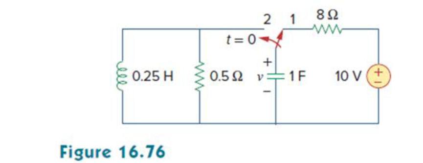
In the circuit of Fig. 16.76, the switch has been in position 1 for a long time but moved to position 2 at t = 0. Find:
- (a) v(0+), dv(0+)/dt
- (b) v(t) for t ≥ 0.
a.
Find the value of
Answer to Problem 53P
The value of
Explanation of Solution
Given data:
Refer to Figure 16.76 in the textbook.
The switch is in position 1 for a long time and moved to position 2 at
Calculation:
The given circuit is redrawn as shown in Figure 1.
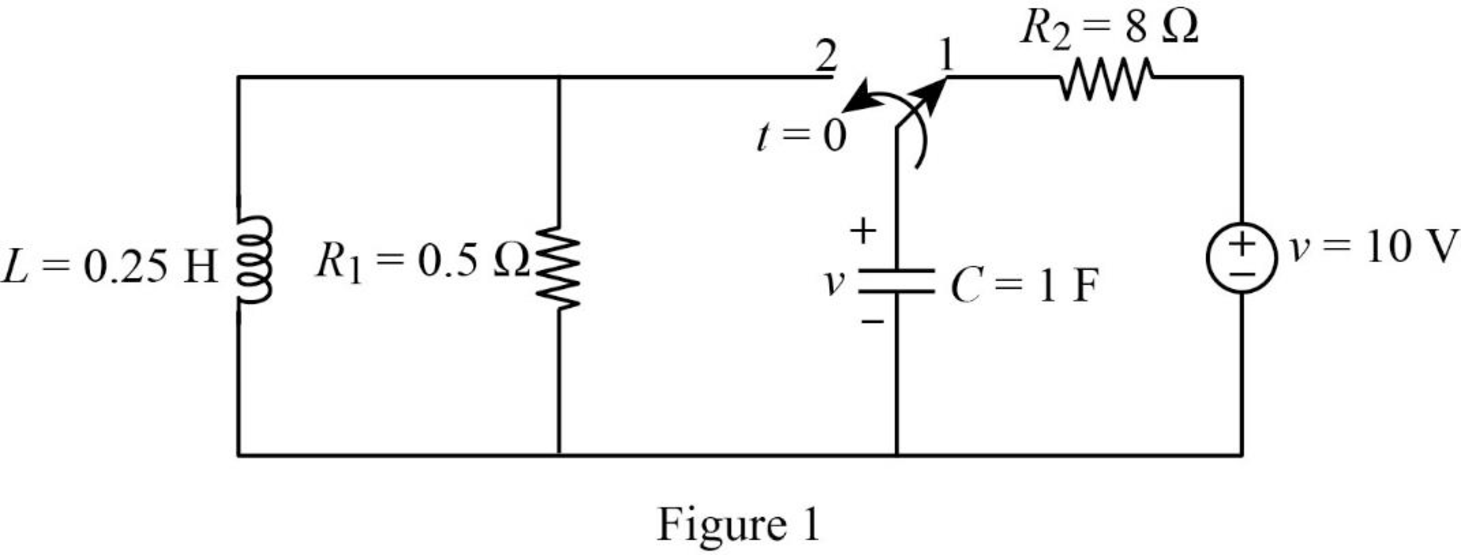
For a DC circuit, at steady state condition when the switch is in position ‘1’at time
Now, the Figure 1 is reduced as shown in Figure 2.
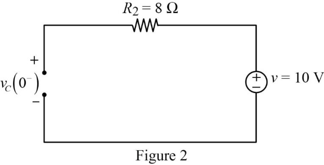
Refer to Figure 2, the voltage across the resistor is same as the voltage across the capacitor which is the source voltage.
The current through inductor and voltage across capacitor is always continuous so that,
When the switch is in position ‘2’, the Figure 1 is reduced as shown in Figure 3.
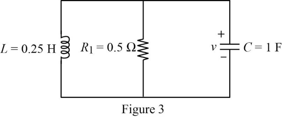
Refer to Figure 3, the capacitor, resistor and inductor are connected in parallel. For the parallel connection the voltage is same. In Figure 3, the magnitude of voltage is in opposite direction.
Apply Kirchhoff’s current law for Figure 3.
Substitute
Write an expression to calculate the current through resistor.
Substitute
Substitute
Substitute
At time
Rearrange the above equation to find
Substitute
Conclusion:
Thus, the value of
b.
Find the expression of voltage
Answer to Problem 53P
The expression of voltage
Explanation of Solution
Formula used:
Write a general expression to calculate the impedance of a resistor in s-domain.
Here,
Write a general expression to calculate the impedance of an inductor in s-domain.
Here,
Write a general expression to calculate the impedance of a capacitor in s-domain.
Here,
Calculation:
Substitute
Substitute
Substitute
Using element transformation methods with initial conditions convert the Figure 3 into s-domain.
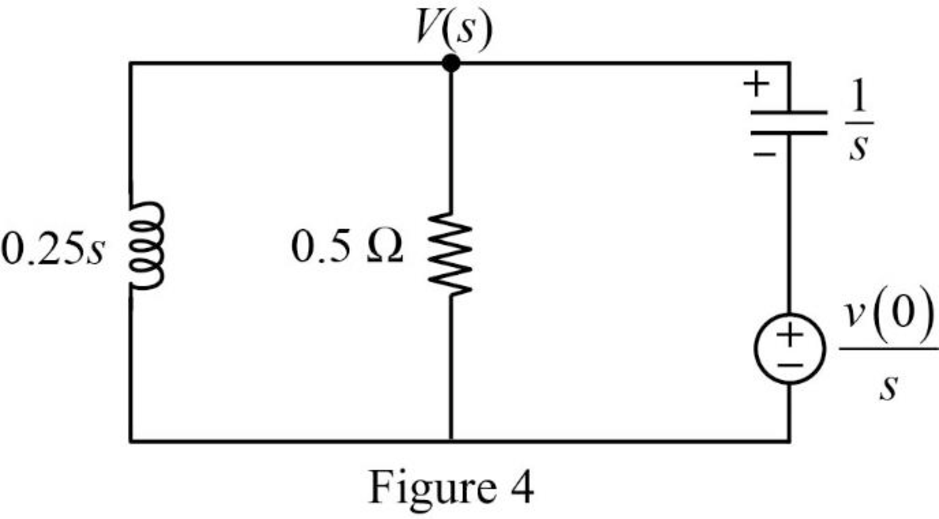
Apply nodal analysis at node
Substitute
Simplify the above equation to find
From the above equation , the characteristic equation is
Write a general expression to calculate the roots of quadratic equation
Comparing the equation (6) with the equation
Substitute
Simplify the above equation to find
Substitute the roots of characteristic equation in equation (5) to find
Take partial fraction for above equation.
The equation (8) can also be written as follows:
Simplify the above equation as follows:
Substitute
Simplify the above equation to find
Substitute
Simplify the above equation to find
Substitute
Take inverse Laplace transform for above equation to find
Simplify the above equation to find
Conclusion:
Thus, the expression of voltage
Want to see more full solutions like this?
Chapter 16 Solutions
Fundamentals of Electric Circuits


- Using convolution, find the response of the following system: x"+4x=F(t) F(t)=cos2t+3, 0arrow_forwardR For the RL circuit, find the mathematical model (input-output relationship) if the output is the inductor voltage, VL(t)=y(t) and R=13 0, L=5 H. O a. x'(t) = y'(t)+2,60y'(t) O b. x'(t) = y'(t)+ 2,60y(t) O c x(t) = y(t)'+ 0,38y(t) O d. x(t) = y(t)+ 2,60y'(t) O e. x'(t) = y'(t)+ 0,38y(t) O f. x(t) = y(t)+ 0,38y'(t) O g. x(t) = y(t)+ 0,38y(t) O h. x'(t) = y(t)+ 2,60y(t)arrow_forwardDesign a TG circuit for F = AX +BY+ CZ where X,Y and Z are inputs and A,B and C are gate controls for TG.arrow_forwardLet Y(s) be the unit-step response of a causal system, having a transfer function 3-S G(s) = (s+ 1)(s+ 3) that is, Y(s) = G(s) The forced response of the system is (a) u(t) (b) 2u(t) (c) u(t) - 2e'u(t) + e 3tu(t) (d) 2u(t) - 2eu(t) + e 3tu(t)arrow_forward. Find the overall transfer function for the given system and also find the value of BS to make damping ratio 8 of the given system is equal to 0.5. R(S) D K=2 5 S (5+2) BS C(s)arrow_forwardIf the input of a first order system is a unit step, the step response is c (t) = 1-exp (-at) Select one: O a. True O b. Falsearrow_forwardX R For the RL circuit, find the mathematical model (input-output relationship) if the output is the inductor voltage, V₁(t)=y(t) and R=17 Q2, L=5 H. (Watch out for the derivative symbol!)arrow_forwardUSE THE CIRCUITS IN THE S-DOMAIN The parameter values for the circuit in are as follows: R=1kΩ,L=12.5H,C=2μF, and Idc=30mA. I need to find vo(t) for t≥0, Find io(t) for t≥0.3. Does your solution for io(t) make sense when t=0?arrow_forwardAssuming zero initial condition, the response y(t) of the system given below to a unit step input u(t) is U(s) Y(s) (A) u(t) (B) tu(t) (C (D) e* u(t) 117arrow_forwardarrow_back_iosSEE MORE QUESTIONSarrow_forward_ios
 Introductory Circuit Analysis (13th Edition)Electrical EngineeringISBN:9780133923605Author:Robert L. BoylestadPublisher:PEARSON
 Delmar's Standard Textbook Of ElectricityElectrical EngineeringISBN:9781337900348Author:Stephen L. HermanPublisher:Cengage Learning
 Programmable Logic ControllersElectrical EngineeringISBN:9780073373843Author:Frank D. PetruzellaPublisher:McGraw-Hill Education
 Fundamentals of Electric CircuitsElectrical EngineeringISBN:9780078028229Author:Charles K Alexander, Matthew SadikuPublisher:McGraw-Hill Education
 Electric Circuits. (11th Edition)Electrical EngineeringISBN:9780134746968Author:James W. Nilsson, Susan RiedelPublisher:PEARSON
 Engineering ElectromagneticsElectrical EngineeringISBN:9780078028151Author:Hayt, William H. (william Hart), Jr, BUCK, John A.Publisher:Mcgraw-hill Education,