
Fundamentals of Electric Circuits
6th Edition
ISBN: 9780078028229
Author: Charles K Alexander, Matthew Sadiku
Publisher: McGraw-Hill Education
expand_more
expand_more
format_list_bulleted
Videos
Textbook Question
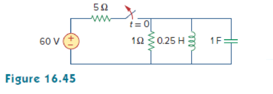
Chapter 16, Problem 22P
Find the voltage across the capacitor as a function of time for t > 0 for the circuit in Fig. 16.45. Assume steady-state conditions exist at t = 0–.
Expert Solution & Answer
Want to see the full answer?
Check out a sample textbook solution
Students have asked these similar questions
9.pdf - Adobe Acrobat Reader DC (64-bit)
ndow Help
FINAL EP QP_SEM . x
Sign In
10 / 12
116%
Search Combine PDF
Export PDF
A capacitor is charged with 50 mC in a time of 20 uS. If the energy stored in the capacitor is 5 J,
Edit PDF
find (i) voltage across the capacitor, (ii) current through the capacitor and (iii) value of capacitance.
Create PDF
EComment
Combine Files
E0 Organize Pag
Delete, insert, extract and
rotate pages.
Try now
Convert, edit and e-sign P
The question concearns RLC circuit, i have 2 sets of data, I need to calculate Z (impedance), R (resistance), Xl (inductive reactance), Xc (capacitive reactance), L (inductance) and C (capacitance) for every measurement in the PDF (first pdf is what do those numbers mean, second pdf is the measurement). I do not know how to calculate it, I do not know the formulas to do that. Please calculate it and show me formula how to calculate it. In this RL parallel load, do i need to calculate all the things i wrote above?
The question concearns RLC circuit, i have 2 sets of data, I need to calculate Z (impedance), R (resistance), Xl (inductive reactance), Xc (capacitive reactance), L (inductance) and C (capacitance) for every measurement in the PDF (first pdf is what do those numbers mean, second pdf is the measurement). I do not know how to calculate it, I do not know the formulas to do that. Please calculate it and show me formula how to calculate it. In this pure inductive load, do i need to calculate all the things i wrote above?
Chapter 16 Solutions
Fundamentals of Electric Circuits
Ch. 16.2 - Determine vo(t) in the circuit of Fig. 16.6,...Ch. 16.2 - Prob. 2PPCh. 16.2 - Prob. 3PPCh. 16.3 - For the circuit shown in Fig. 16.12 with the same...Ch. 16.3 - Prob. 5PPCh. 16.3 - The initial energy in the circuit of Fig. 16.17 is...Ch. 16.4 - Prob. 7PPCh. 16.4 - Prob. 8PPCh. 16.4 - Prob. 9PPCh. 16.5 - Obtain the state variable model for the circuit...
Ch. 16.5 - Prob. 11PPCh. 16.5 - Prob. 12PPCh. 16.6 - For what value of is the circuit in Fig. 16.29...Ch. 16.6 - Prob. 14PPCh. 16.6 - Prob. 15PPCh. 16.6 - Synthesize the function Vo(s)Vin=2ss2+6s+10 using...Ch. 16 - Prob. 1RQCh. 16 - The current through an RL series circuit with...Ch. 16 - Prob. 3RQCh. 16 - Prob. 4RQCh. 16 - Prob. 5RQCh. 16 - Prob. 6RQCh. 16 - Prob. 7RQCh. 16 - Prob. 8RQCh. 16 - Prob. 9RQCh. 16 - Prob. 10RQCh. 16 - The current in an RLC circuit is described by...Ch. 16 - The differential equation that describes the...Ch. 16 - Prob. 3PCh. 16 - If R = 20 , L = 0.6 H, what value of C will make...Ch. 16 - The responses of a series RLC circuit are vc(t) =...Ch. 16 - Prob. 6PCh. 16 - Prob. 7PCh. 16 - Prob. 8PCh. 16 - Prob. 9PCh. 16 - The step responses of a series RLC circuit are Vc...Ch. 16 - The step response of a parallel RLC circuit is v =...Ch. 16 - Prob. 12PCh. 16 - Prob. 13PCh. 16 - Prob. 14PCh. 16 - For the circuit in Fig. 16.38. calculate the value...Ch. 16 - The capacitor in the circuit of Fig. 16.39 is...Ch. 16 - If is(t) = 7.5e2t u(t) A in the circuit shown in...Ch. 16 - Find v(t), t 0 in the circuit of Fig. 16.41. Let...Ch. 16 - The switch in Fig. 16.42 moves from position A to...Ch. 16 - Find i(t) for t 0 in the circuit of Fig. 16.43.Ch. 16 - In the circuit of Fig. 16.44, the switch moves...Ch. 16 - Find the voltage across the capacitor as a...Ch. 16 - Obtain v (t) for t 0 in the circuit of Fig....Ch. 16 - The switch in the circuit of Fig. 16.47 has been...Ch. 16 - Calculate v(t) for t 0 in the circuit of Fig....Ch. 16 - Prob. 26PCh. 16 - Find v (t) for t 0 in the circuit in Fig. 16.50.Ch. 16 - For the circuit in Fig. 16.51, find v(t) for t 0.Ch. 16 - Prob. 29PCh. 16 - Find vo(t), for all t 0, in the circuit of Fig....Ch. 16 - Prob. 31PCh. 16 - For the network in Fig. 16.55, solve for i(t) for...Ch. 16 - Using Fig. 16.56, design a problem to help other...Ch. 16 - Prob. 34PCh. 16 - Prob. 35PCh. 16 - Prob. 36PCh. 16 - Prob. 37PCh. 16 - The switch in the circuit of Fig. 16.61 is moved...Ch. 16 - Prob. 39PCh. 16 - Prob. 40PCh. 16 - Prob. 41PCh. 16 - Prob. 42PCh. 16 - Prob. 43PCh. 16 - Prob. 44PCh. 16 - Find v(t) for t 0 in the circuit in Fig. 16.68.Ch. 16 - Prob. 46PCh. 16 - Determine io(t) in the network shown in Fig....Ch. 16 - Prob. 48PCh. 16 - Find i0(t) for t 0 in the circuit in Fig. 16.72....Ch. 16 - Prob. 50PCh. 16 - In the circuit of Fig. 16.74, find i(t) for t 0.Ch. 16 - Prob. 52PCh. 16 - In the circuit of Fig. 16.76, the switch has been...Ch. 16 - Prob. 54PCh. 16 - Prob. 55PCh. 16 - Calculate io(t) for t 0 in the network of Fig....Ch. 16 - Prob. 57PCh. 16 - Prob. 58PCh. 16 - Find vo(t) in the circuit of Fig. 16.82 if vx(0) =...Ch. 16 - Prob. 60PCh. 16 - Prob. 61PCh. 16 - Using Fig. 16.85, design a problem to help other...Ch. 16 - Consider the parallel RLC circuit of Fig. 16.86....Ch. 16 - The switch in Fig. 16.87 moves from position 1 to...Ch. 16 - For the RLC circuit shown in Fig. 16.88, find the...Ch. 16 - For the op amp circuit in Fig. 16.89, find v0(t)...Ch. 16 - Given the op amp circuit in Fig. 16.90, if v1(0+)...Ch. 16 - Prob. 68PCh. 16 - Prob. 69PCh. 16 - Using Fig. 16.93, design a problem to help other...Ch. 16 - Prob. 71PCh. 16 - The transfer function of a system is H(s)=s23s+1...Ch. 16 - Prob. 73PCh. 16 - Design a problem to help other students better...Ch. 16 - Prob. 75PCh. 16 - For the circuit in Fig. 16.95, find H(s) =...Ch. 16 - Obtain the transfer function H(s) = VoVs for the...Ch. 16 - Prob. 78PCh. 16 - For the circuit in Fig. 16.97, find: (a) I1/Vs (b)...Ch. 16 - Refer to the network in Fig. 16.98. Find the...Ch. 16 - Prob. 81PCh. 16 - Prob. 82PCh. 16 - Refer to the RL circuit in Fig. 16.101. Find: (a)...Ch. 16 - A parallel RL circuit has R = 4 and L = 1 H. The...Ch. 16 - Prob. 85PCh. 16 - Prob. 86PCh. 16 - Prob. 87PCh. 16 - Prob. 88PCh. 16 - Develop the state equations for the circuit shown...Ch. 16 - Prob. 90PCh. 16 - Prob. 91PCh. 16 - Prob. 92PCh. 16 - Prob. 93PCh. 16 - Prob. 94PCh. 16 - Prob. 95PCh. 16 - Prob. 96PCh. 16 - A system is formed by cascading two systems as...Ch. 16 - Determine whether the op amp circuit in Fig....Ch. 16 - It is desired realize the transfer function...Ch. 16 - Prob. 100PCh. 16 - Prob. 101PCh. 16 - Synthesize the transfer function...Ch. 16 - Prob. 103CPCh. 16 - Prob. 104CPCh. 16 - Prob. 105CP
Knowledge Booster


Learn more about
Need a deep-dive on the concept behind this application? Look no further. Learn more about this topic, electrical-engineering and related others by exploring similar questions and additional content below.Similar questions
- The question concearns RLC circuit, i have 2 sets of data, I need to calculate Z (impedance), R (resistance), Xl (inductive reactance), Xc (capacitive reactance), L (inductance) and C (capacitance) for every measurement in the PDF (first pdf is what do those numbers mean, second pdf is the measurement). I do not know how to calculate it, I do not know the formulas to do that. Please calculate it and show me formula how to calculate it. In this pure resistive load, do i need to calculate all the things i wrote above?arrow_forwarddoos goo lorms/d/e/1FAlpQLSeis9wjiqvOVB12Eo71MGSVR7NxRXIP Join a Meeting- .. movies.awesomese.. O d ll O ag Question The general solution of the following differential equation y(5) – y' = 4x is: y(x) = ce + cze2* + cg cos(2x) y(x) = +cze" + Cge*+ Cq cos(x) +q, sin(2x) - 2x +cg sin(x) – 2x? This option This option y(x) - ce + czeco s(V3x) y(x) = ce + cye 2* + cg cos(2x) ta sin(2x) + Ax + B +ege "si n(v3x) + Ax + B This option This optionarrow_forward6. A LRC circuit below is used to modify an input voltage V, = wsin(@t) +2w cos(w1). For this application, R = 2 2. L= 2 H und C F.Your differential equation must be in terms of 20 charge q. You must use the complimentary and particular solution method as shown in your notes to generate the general solution. No other method will be accepted. Use two decimal point accuracy. You are given that -2No? +20N = 20 and -2Mw + 20M = 2w, which you must use to simplify your particular solution when you equate coefficients. C Va ko - 1 sin(et)arrow_forward
- 16. 7.16 What percentage of the initial energy stored in the inductor in thecircuit is dissipated by the current-controlled voltagesource?arrow_forwardQ.15: The switch has been in position "a" for a long time. At t=0 the switch is moved to position "b". Use classical method to find the voltage across and current through the capacitor as a function of time? (Ans.: Vc(t)=80[1.25-e 20 b1002 10m H t%3D0S 30V 42 100V 2uF 5000t -5000t (cos5000t+sin5000t)] V & ic(t)=1.6e sin5000t A)arrow_forwardDetermine the exact solution of the following differential equation y = 2 - y at y(0)=1. So the value of y(1.5) is .. O a. 1.753 Ob. 1.777 O c None of options O d. 1.798 O e. 1.699arrow_forward
- A series RC circuit is driven by a voltage source step function. The voltage values across the capacitor begins to rise as a function of time as follows: T( time in seconds) VC voltage across capacitor 10 20 30 40 50 60 70 2.922 4.776 5.954 6.701 7.175 7.476 7.669 Determine which fit is best: linear, power, or exponential for VC vs time (show plots) Plot the raw data and best fitted line from the models above. Find the equation for the best-fit modelarrow_forwardAn RC circuit has an emf of 10 sin t (volts), a resistance of 100 ohms, a capacitance of 0.005 farad, and no initial charge on the capacitor. D. 13. What is the differential equation governing the amount of charge on the capacitor? * 14. What is the integrating factor of your answer in 13? * 15. What is the charge on the capacitor at any time t? * 16. What is the current in the circuit at any time t.arrow_forwardFind the voltage drop across the inductor ????1(??) and capacitor ????(??). Write your answers inpolar formarrow_forward
- The pathway for a binary electrical signal between gates in an integrated circuit can be modeled as an RC circuit, as shown in the figure to the right; the voltage source models the transmitting gate, and the R. capacitor models the receiving gate. Suppose the resistance is 400 2 and the capacitance is 10 - 11 F (10 picofarads, pF). If the capacitor is initially uncharged and the transmitting gate changes instantaneously from 0 to 4 V, how long will it take for the voltage at the receiving gate to reach 3 V? E What is the charge q(t) on the capacitor at time t? q(t) =arrow_forwardAn AC bridge circuit the supply voltage is 20 V at 500 Hz. Arm AB is 0.25 µF pure capacitance; arm BD is 400 0 pure resistance and arm AC has a 120 Q resistance in parallel with a 0.15 µF capacitor. Find resistance and inductance or capacitance of the arm CD considering it as a series circuitarrow_forwardThe pathway for a binary electrical signal between gates in an integrated circuit can be modeled as an RC circuit, as shown in the figure to the right; the voltage source models the transmitting gate, and the capacitor models the receiving gate. Suppose the resistance is 300 2 and the capacitance is 10 F (100 picofarads, pF). If the capacitor is initially uncharged and the transmitting gate changes instantaneously from 0 to 4 V, how long will it take for the voltage at the receiving gate to reach 3 V? 10 R www E It will take seconds. (Type your answer in scientific notation, using the appropriate symbol from the math palette for any multiplication. Round to three decimal places as needed.)arrow_forward
arrow_back_ios
SEE MORE QUESTIONS
arrow_forward_ios
Recommended textbooks for you
 Introductory Circuit Analysis (13th Edition)Electrical EngineeringISBN:9780133923605Author:Robert L. BoylestadPublisher:PEARSON
 Delmar's Standard Textbook Of ElectricityElectrical EngineeringISBN:9781337900348Author:Stephen L. HermanPublisher:Cengage Learning
 Programmable Logic ControllersElectrical EngineeringISBN:9780073373843Author:Frank D. PetruzellaPublisher:McGraw-Hill Education
 Fundamentals of Electric CircuitsElectrical EngineeringISBN:9780078028229Author:Charles K Alexander, Matthew SadikuPublisher:McGraw-Hill Education
 Electric Circuits. (11th Edition)Electrical EngineeringISBN:9780134746968Author:James W. Nilsson, Susan RiedelPublisher:PEARSON
 Engineering ElectromagneticsElectrical EngineeringISBN:9780078028151Author:Hayt, William H. (william Hart), Jr, BUCK, John A.Publisher:Mcgraw-hill Education,
Introductory Circuit Analysis (13th Edition)
Electrical Engineering
ISBN:9780133923605
Author:Robert L. Boylestad
Publisher:PEARSON
Delmar's Standard Textbook Of Electricity
Electrical Engineering
ISBN:9781337900348
Author:Stephen L. Herman
Publisher:Cengage Learning
Programmable Logic Controllers
Electrical Engineering
ISBN:9780073373843
Author:Frank D. Petruzella
Publisher:McGraw-Hill Education
Fundamentals of Electric Circuits
Electrical Engineering
ISBN:9780078028229
Author:Charles K Alexander, Matthew Sadiku
Publisher:McGraw-Hill Education
Electric Circuits. (11th Edition)
Electrical Engineering
ISBN:9780134746968
Author:James W. Nilsson, Susan Riedel
Publisher:PEARSON
Engineering Electromagnetics
Electrical Engineering
ISBN:9780078028151
Author:Hayt, William H. (william Hart), Jr, BUCK, John A.
Publisher:Mcgraw-hill Education,
Routh Hurwitz Stability Criterion Basic Worked Example; Author: The Complete Guide to Everything;https://www.youtube.com/watch?v=CzzsR5FT-8U;License: Standard Youtube License