
Videos
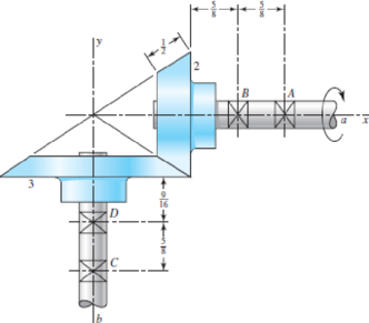
The figure shows a 10 diametral pitch 18-tooth 20° straight bevel pinion driving a 30-tooth gear. The transmitted load is 25 lbf. Find the bearing reactions at C and D on the output shaft if D is to take both radial and thrust loads.
Problem 13–44
Dimensions in inches.
The bearing reaction at
The bearing reaction at
Answer to Problem 44P
The bearing reaction at
The bearing reaction at
Explanation of Solution
The figure below shows the forces acting at the bevel gear and pinion assembly.
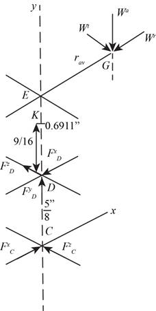
Figure-(1)
Write the expression for the diameter of gear 2.
Here, the diametrical pitch is
Write the expression for the diameter of gear 3.
Here, the number of teeth on gear 3 is
Write the expression for the pitch angle for gear 2.
Write the expression for the pitch angle for gear 3.
Write the expression fort the pitch radius at the mid-point of the bevel gear.
Here, the lateral side of the gear 2 is
Write the expression for
Here, the distance between the points
Write the expression for the radial load.
Here, the pressure angle is
Write the expression for the axial load.
Write the expression of the load in vector form.
Write the expression for the position vector of
Write the expression for the position vector of
Write the expression for the force on the bearing
Here, the force on bearing
Write the expression for the moment about
Here, the torque is
Write the expression for the force equilibrium for the set of bearings.
Substitute
Conclusion:
Substitute
Substitute
Substitute
Substitute
Substitute
Substitute
Substitute
Substitute
Substitute
Substitute
Compare the
Compare the
Compare the
Substitute
Thus, the bearing reaction at
Substitute
Thus, the bearing reaction at
Want to see more full solutions like this?
Chapter 13 Solutions
Shigley's Mechanical Engineering Design (McGraw-Hill Series in Mechanical Engineering)


- The figure shows a pair of shaft-mounted spur gears having a module of 5 mm with an 18-tooth 20° pressure angle pinion driving a 45-tooth gear. The power input is 24 kW at 1800 rev/min counterclockwise into the pinion. Find the direction and magnitude of the forces acting on the shafts a and b. SOLUTION:arrow_forwardA pinion having 40 teeth drives a gear having 80 teeth. the profile of the gear is involute with pressure angle ( 22), 12 mm module and (14) mm addendum. Find 1-the length of contact2-Arc of contact 3-Contact ratioarrow_forwardThe figure shows a pair of shaft-mounted spur gears having a diametral pitch of 5 teeth/in with an 18-tooth 20° pinion driving a 45-tooth gear. The power input is 28-hp at 1700 rev/min. Find the magnitude of the force acting on bearing D. 3 2 3 in 3 in The magnitude of the force acting on bearing Dis lbf.arrow_forward
- 13-31 Shaft a in the figure has a power input of 75 kW at a speed of 1000 rev/min in the counterclock- wise direction. The gears have a module of 5 mm and a 20° pressure angle. Gear 3 is an idler. (a) Find the force F3, that gear 3 exerts against shaft b. (b) Find the torque T4, that gear 4 exerts on shaft c. 517 34T Problem 13-31 3 177arrow_forwardQuestion 1: The figure shows a 16T 20° straight bevel pinion driving a 32T gear, and the location of the bearing centerlines. Pinion shaft a receives 2.5 hp at 248 rev/min. Determine the bearing reactions at A and B if A is to take both radial and thrust loads. On-Screen Keyboard Esc 1 3. 4 5 6.arrow_forwardQ8/ An epicyclic reduction gear shown in figure, has a shaft A fixed to arm. The arm has a pin fixed to its outer end and two gears C and E which are rigidly fixed (C-E compound gear) revolve on this pin. Gear C meshes with annular gear D and gear E with pinion F. G is the driver gear and D is kept stationary. The number of the teeth is as follows: Tp = 80, Tc =10, TE = 24 and Tp = 10. The gear G runs at 200 rpm, find the speed of shaft A. (Area ge Darrow_forward
- A 20° 20-tooth cast-iron spur pinion having a module of 4 mm drives a 32-tooth cast-iron gear. Find the contact stress if the pinion speed is 1020 rev/min, the face width is 50 mm, and 10 kW of power is transmitted. Refer to table number 14-8 for elastic coefficient. The contact stress is MPa.arrow_forwardIn the double-reduction gear train shown (dimensions are in inches), shaft a is driven by a motor attached by a flexible coupling attached to the overhang. The motor provides a torque of 2500 lbf-in at a speed of 1200 rpm. The gears have 20° pressure angles, with diameters shown in the figure. Use an AISI 1020 cold-drawn steel. Design Shaft CD with a design factor of 1.5 by performing the following tasks. (a) Sketch a general shaft layout, including means to locate the gears and bearings, and to transmit the torque. (b) Perform a force analysis to find the bearing reaction forces, and generate shear and bending moment diagrams. (c) Determine potential critical locations for stress design. (d) Determine critical diameters of the shaft based on fatigue and static stresses at the critical locations. (e) Make any other dimensional decisions necessary to specify all diameters and axial dimensions. Sketch the shaft to scale, showing all proposed dimensions. (f) If any of the deflections…arrow_forwardProblem 5. A speed reducer has 20 degree full-depth teeth and consists of a 22-tooth steel spur pinion driving a 60-tooth cast-iron gear. The horsepower transmitted is 15 at a pinion speed of 1200 rev/min. For a diametral pitch of 6 teeth/in and a face width of 2 in, find the contact stress.arrow_forward
- Task 3 The figure shows a pair of shaft-mounted spur gears having an 18-tooth pinion driving a 45- tooth gear. The power input is 32-hp at 1800 rev/min. Find the torque on each gear. Find also the power output. 3 in' 3 inarrow_forwardThe figure shows a double-reduction helical gearset. Pinion 2 is the driver, and it receives a torque of 1200 Ibf • in from its shaft in the direction shown. Pinion 2 has a normal diametral pitch of 8 teeth/in, 14 teeth, and a normal pressure angle of 20° and is cut right-handed with a helix angle of 30°. The mating gear 3 on shaft b has 36 teeth. Gear 4, which is the driver for the second pair of gears in the train, has a normal diametral pitch of 3 teeth/in, 15 teeth, and a normal pressure angle of 20° and is cut left-handed with a helix angle of 15°. Mating gear S has 45 teeth. Find the magnitude and direction of the force exerted by the bearings C and D on shaft b if bearing C can take only a radial load while bearing D is mounted to take both radial and thrust loads.arrow_forwardShaft a in the figure has a power input of 75 kW at a speed of 1000 rev/min in the counterclockwise direction. The gears have a module of 5 mm and a 20° pressure angle. Gear 3 is an idler (b) Find the torque T4c that gear 4 exerts on shaft c.arrow_forward
 Elements Of ElectromagneticsMechanical EngineeringISBN:9780190698614Author:Sadiku, Matthew N. O.Publisher:Oxford University Press
 Mechanics of Materials (10th Edition)Mechanical EngineeringISBN:9780134319650Author:Russell C. HibbelerPublisher:PEARSON
 Thermodynamics: An Engineering ApproachMechanical EngineeringISBN:9781259822674Author:Yunus A. Cengel Dr., Michael A. BolesPublisher:McGraw-Hill Education
 Control Systems EngineeringMechanical EngineeringISBN:9781118170519Author:Norman S. NisePublisher:WILEY
 Mechanics of Materials (MindTap Course List)Mechanical EngineeringISBN:9781337093347Author:Barry J. Goodno, James M. GerePublisher:Cengage Learning
 Engineering Mechanics: StaticsMechanical EngineeringISBN:9781118807330Author:James L. Meriam, L. G. Kraige, J. N. BoltonPublisher:WILEY