
Shigley's Mechanical Engineering Design (McGraw-Hill Series in Mechanical Engineering)
10th Edition
ISBN: 9780073398204
Author: Richard G Budynas, Keith J Nisbett
Publisher: McGraw-Hill Education
expand_more
expand_more
format_list_bulleted
Concept explainers
Videos
Textbook Question
thumb_up100%
Chapter 13, Problem 29P
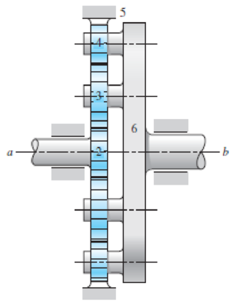
Tooth numbers for the gear train shown in the figure are N2 = 12, N3 = 16, and N4 = 12. How many teeth must internal gear 5 have? Suppose gear 5 is fixed. What is the speed of the arm if shaft a rotates at 320 rev/min counterclockwise as viewed from the left side of the figure?
Problem 13-29
Expert Solution & Answer
Want to see the full answer?
Check out a sample textbook solution
Students have asked these similar questions
A 20 straight-tooth bevel pinion having 14 teeth and a diametral pitch of 4
teeth/in drives a 30-tooth gear. The two shafts are at right angles and in the same
plane.
The illustration below shows a typical right-angle bevel gear set.
Bevel gear pitch diameters are measured on the outside face along the back-cone,
as shown in the figure.
As shown in figure 13-35, the resultant force acts at the average radius of the
gear/pinion.
If the power transmitted by the pinion is 10 at 1,453 rpm, calculate the pinion
tangent force in lbf.
Cone distance A
Face
Pitch angle
Pitch angle
Back
cone
Uniform
clearance
Pitch diameter Da
Back-cone
radius,
h
ASAP
The figure shows a schematic representation of a gear system. The gears are meshed with one
another and can therefore not slip. The ring gear R is fixed, i.e. wR = 0. Gear A has an inner hub
with radius rA(inner) = 0.3 m which is fixed to the rest of the gear, having a radius of FAlouter) = 0.8
m, and moves together as a unit. Gear A is in mesh with gear B which has a diameter of de = 1.5
m. Gear B has a clockwise angular velocity of wg = 2.1 rad/s. Determine the angular speed of gear
A.
B
TA(outer
R
Chapter 13 Solutions
Shigley's Mechanical Engineering Design (McGraw-Hill Series in Mechanical Engineering)
Ch. 13 - A 17-tooth spur pinion has a diametral pitch of 8...Ch. 13 - A 15-tooth spur pinion has a module of 3 mm and...Ch. 13 - A spur gearset has a module of 6 mm and a velocity...Ch. 13 - A 21-tooth spur pinion mates with a 28-tooth gear....Ch. 13 - A 20 straight-tooth bevel pinion having 14 teeth...Ch. 13 - A parallel helical gearset uses a 20-tooth pinion...Ch. 13 - A parallel helical gearset consists of a 19-tooth...Ch. 13 - To avoid the problem of interference in a pair of...Ch. 13 - Prob. 9PCh. 13 - Prob. 10P
Ch. 13 - Prob. 11PCh. 13 - Prob. 12PCh. 13 - Prob. 13PCh. 13 - Prob. 14PCh. 13 - A parallel-shaft gearset consists of an 18-tooth...Ch. 13 - The double-reduction helical gearset shown in the...Ch. 13 - Shaft a in the figure rotates at 600 rev/min in...Ch. 13 - The mechanism train shown consists of an...Ch. 13 - The figure shows a gear train consisting of a pair...Ch. 13 - A compound reverted gear trains are to be designed...Ch. 13 - Prob. 21PCh. 13 - Prob. 22PCh. 13 - Prob. 23PCh. 13 - A gearbox is to be designed with a compound...Ch. 13 - The tooth numbers for the automotive differential...Ch. 13 - Prob. 26PCh. 13 - In the reverted planetary train illustrated, find...Ch. 13 - Prob. 28PCh. 13 - Tooth numbers for the gear train shown in the...Ch. 13 - The tooth numbers for the gear train illustrated...Ch. 13 - Shaft a in the figure has a power input of 75 kW...Ch. 13 - The 24T 6-pitch 20 pinion 2 shown in the figure...Ch. 13 - The gears shown in the figure have a module of 12...Ch. 13 - The figure shows a pair of shaft-mounted spur...Ch. 13 - Prob. 35PCh. 13 - Prob. 36PCh. 13 - A speed-reducer gearbox containing a compound...Ch. 13 - For the countershaft in Prob. 3-72, p. 152, assume...Ch. 13 - Prob. 39PCh. 13 - Prob. 40PCh. 13 - Prob. 41PCh. 13 - Prob. 42PCh. 13 - The figure shows a 16T 20 straight bevel pinion...Ch. 13 - The figure shows a 10 diametral pitch 18-tooth 20...Ch. 13 - Prob. 45PCh. 13 - The gears shown in the figure have a normal...Ch. 13 - Prob. 47PCh. 13 - Prob. 48PCh. 13 - Prob. 49PCh. 13 - The figure shows a double-reduction helical...Ch. 13 - A right-hand single-tooth hardened-steel (hardness...Ch. 13 - The hub diameter and projection for the gear of...Ch. 13 - A 2-tooth left-hand worm transmits 34 hp at 600...
Knowledge Booster


Learn more about
Need a deep-dive on the concept behind this application? Look no further. Learn more about this topic, mechanical-engineering and related others by exploring similar questions and additional content below.Similar questions
- An epicyclic gear train is shown schematically in the adjacent figure. The sun gear 2 on the input shaft is a 20 teeth external gear. The planet gear 3 is a 40 teeth external gear. The ring gear 5 is a 100 teeth internal gear. The ring gear 5 is fixed and the gear 2 is rotating at 60 rpm ccw (ccw= counterclockwise and cw= clockwise) %3D 3 4 The arm 4 attached to the output shaft will rotate at (а) 10 rpm сCW (b) 10 rpm cw (c) 12 rpm CW (d) 12 rpm ccW 2.arrow_forwardA planetary gear train is shown in the figure. The sun gear (gear 1) is fixed, it has a 1-in. pitch diameter with a diametral pitch of 12. Gear 3 has 36 teeth and gear 4 has 20 teeth. Gear 5 has 40 teeth and is keyed to the same shaft as gear 4. Gear 5 mates with the ring gear (gear 6), which serves as the output from the train and has 160 teeth. The carrier (link 2) serves as the input to the train, determine the rotational velocity of the ring gear when the input shaft rotates at 1125 rpm clockwise.arrow_forwardFor the gear train shown in the figure. Planet gears 3, 4, and 5 are rigidly connected to a common concentric shaft and turn at the same rotational speed, W3 = W4 = W5. Gear 1 is connected to the input, gear 7 is connected to the output, and gear 6 is fixed. The planet carrier component 2 is connected to neither an input nor an output. Use the Tabular method to fill up the table and determine a) the speed of gear 7 if the speed of gearl is 30 RPM. b) The ratio between the input and the output. N₁ = 10, N3 = 24, N4 = 12, N₁ = 12, No = 20, N₁ = 30 Gears All locked turn at x RPM Crank is fixed, Gear 6 turns at y RPM Absolute rpm Gearl Input Fixed Gear6 Gear7 * Outputarrow_forward
- An epicyclic gear train is shown in the figure below. The number of teeth on the gears A, B and D are 20, 30 and 20, respectively. Gear C has 80 teeth on the inner surface and 100 teeth on the outer surface. If the carrier arm AB is fixed and the sun gear A rotates at 300 rpm in the clockwise direction, then the rpm of D in the clockwise direction is B Darrow_forward4. For the gear train in a watch shown in the following figure. The teeth number are z,=20, z,=40, Z3=18, z4-50, Z5=25, Z6-20, z,=54. Please calculate Speed ratio 17 1 VIIA 3 5 4 6 2 7arrow_forwardFor the gear train illustrated in Figure, determine the output speed and direction of rotation if the input shaft rotates at 1490 rpm clockwise. Gears A to D have a module of 1.5 and gears E to H a module of 2. TA=20 teeth, TD=38 teeth, TE=18 teeth, TG=18 teeth, TH=30 teeth, dB=67.5mm, dC=27 mm and dF =56 mm.arrow_forward
- 2. The following data is for the gear train shown in the figure: Given: N2 = 30t, N3 = 35t, N4 = 55t, N5 = 40t, N6 = 50t, N7 = 40t %3D w2 = 30 rpm ccw, warm = 20 rpm cw, Input torque on gear 2 is 1200 lbf.in Determine the following: a. Angular velocity of the sun gear. b. The gear ratio R required to determine the angular velocity of gear 6. c. The angular velocity of gear 6. d. The angular velocity of gear 7. e. Output torque on gear 7. Be careful with your units. Arm 6 ... 7arrow_forward13-33 The gears shown in the figure have a diametral pitch of 2 teeth per inch and a 20° pressure angl The pinion rotates at 1800 rev/min clockwise and transmits 200 hp through the idler pair to gear 5 on shaft c. What forces do gears 3 and 4 transmit to the idler shaft? Problem 13-33 187 327 187 5 W-487arrow_forwardAn epicyclic gear train is shown schematically in the adjacent figure. The sun gear 2 on the input shaft is a 20 teeth external gear. The planet gear 3 is a 40 teeth external gear. The ring gear 5 is a 100 teeth internal gear. The ring gear 5 is fixed and the gear 2 is rotating at 60 rpm ccw(ccw-counterclockwise and cw- clockwise) 3 2 The arm 4 attached to the output shaft will rotate atarrow_forward
- For the gear train in a watch shown in the following figure. The teeth number are Z1=24, z2=48, Z3=20, Z4=25, z5=1, Z6=40. Please calculate speed ratio i16 4 2 亚 3,arrow_forwardFor the gear train in a watch shown in the following figure. The teeth number are Z1=24, Z2=48, Z3=20, Z4=25, Zs=1, Z6=40. If gear 1 turns up, what is the rotation direction of worm wheel 6? Clockwise or counter-clockwise? (Firstly, you need to judge worm 5 left-handed or right-handed according to the inclined line on it) 4 2 5 亚arrow_forwardThe figure shows a double-reduction helical gearset. Pinion 2 is the driver, and it receives a torque of 1200 Ibf • in from its shaft in the direction shown. Pinion 2 has a normal diametral pitch of 8 teeth/in, 14 teeth, and a normal pressure angle of 20° and is cut right-handed with a helix angle of 30°. The mating gear 3 on shaft b has 36 teeth. Gear 4, which is the driver for the second pair of gears in the train, has a normal diametral pitch of 3 teeth/in, 15 teeth, and a normal pressure angle of 20° and is cut left-handed with a helix angle of 15°. Mating gear S has 45 teeth. Find the magnitude and direction of the force exerted by the bearings C and D on shaft b if bearing C can take only a radial load while bearing D is mounted to take both radial and thrust loads.arrow_forward
arrow_back_ios
SEE MORE QUESTIONS
arrow_forward_ios
Recommended textbooks for you
 Elements Of ElectromagneticsMechanical EngineeringISBN:9780190698614Author:Sadiku, Matthew N. O.Publisher:Oxford University Press
 Mechanics of Materials (10th Edition)Mechanical EngineeringISBN:9780134319650Author:Russell C. HibbelerPublisher:PEARSON
 Thermodynamics: An Engineering ApproachMechanical EngineeringISBN:9781259822674Author:Yunus A. Cengel Dr., Michael A. BolesPublisher:McGraw-Hill Education
 Control Systems EngineeringMechanical EngineeringISBN:9781118170519Author:Norman S. NisePublisher:WILEY
 Mechanics of Materials (MindTap Course List)Mechanical EngineeringISBN:9781337093347Author:Barry J. Goodno, James M. GerePublisher:Cengage Learning
 Engineering Mechanics: StaticsMechanical EngineeringISBN:9781118807330Author:James L. Meriam, L. G. Kraige, J. N. BoltonPublisher:WILEY
Elements Of Electromagnetics
Mechanical Engineering
ISBN:9780190698614
Author:Sadiku, Matthew N. O.
Publisher:Oxford University Press
Mechanics of Materials (10th Edition)
Mechanical Engineering
ISBN:9780134319650
Author:Russell C. Hibbeler
Publisher:PEARSON
Thermodynamics: An Engineering Approach
Mechanical Engineering
ISBN:9781259822674
Author:Yunus A. Cengel Dr., Michael A. Boles
Publisher:McGraw-Hill Education
Control Systems Engineering
Mechanical Engineering
ISBN:9781118170519
Author:Norman S. Nise
Publisher:WILEY
Mechanics of Materials (MindTap Course List)
Mechanical Engineering
ISBN:9781337093347
Author:Barry J. Goodno, James M. Gere
Publisher:Cengage Learning
Engineering Mechanics: Statics
Mechanical Engineering
ISBN:9781118807330
Author:James L. Meriam, L. G. Kraige, J. N. Bolton
Publisher:WILEY
Power Transmission; Author: Terry Brown Mechanical Engineering;https://www.youtube.com/watch?v=YVm4LNVp1vA;License: Standard Youtube License