
Concept explainers
Videos
The 20-mm-diameter steel rod CD is welded to the 20-mm- diameter steel shaft AB as shown. End C of rod CD is touching the rigid surface shown when a couple TB is applied to a disk attached to shaft AB. Knowing that the bearings are self aligning and exert no couples on the shaft, determine the angle of rotation of the disk when TB = 400 N ∙ m. Use E = 200 GPa and G = 77.2 GPa. (Consider the strain energy due to both bending and twisting in shaft AB and to bending in arm CD.)
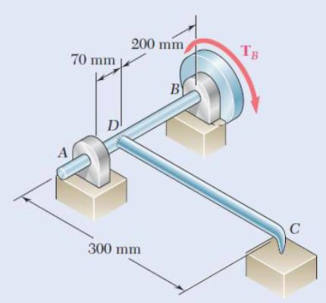
Fig. P11.69
The angle of rotation of the disk when
Answer to Problem 69P
The angle of rotation of the disk at B is
Explanation of Solution
Given information:
The diameter of the shaft AB and the steel rod CD is
The modulus of rigidity
The torque applied at B is
The modulus of elasticity
The length of steel rod CD is
The length of shaft AB is
Calculation:
Calculate the moment of inertia
Substitute
Consider the bending of rod CD.
Sketch the Free Body Diagram as shown in Figure 1.
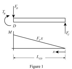
Refer to Figure 1.
Take moment about rod D is Equal to zero.
Substitute
Summation of forces along y direction is Equal to zero.
Calculate the bending moment at a distance x from C as shown below.
Calculate the strain energy as shown below.
For the steel rod CD.
Substitute
Consider the bending of shaft ADB.
Sketch the Free Body Diagram of the shaft as shown in Figure 2.
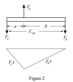
Refer to Figure 2.
Take moment about A is Equal to zero.
Take moment about B is Equal to zero.
Bending moment at a distance x from A
Bending moment at a distance x from B
Calculate the strain energy for shaft AB using Equation (1) as shown below.
Substitute
Substitute
Consider the portion DB of shaft ADB carries the torque.
Calculate the polar moment of inertia
Substitute
Calculate the strain energy
Substitute
Calculate the total strain energy
Substitute
Calculate the angle
Provide the work energy equation at disk B as shown below.
Substitute
Therefore, the angle of rotation of the disk at B is
Want to see more full solutions like this?
Chapter 11 Solutions
Mechanics of Materials, 7th Edition


- The electric motor exerts a 430 N m-torque on the aluminum shaft ABCD when it is rotating at a constant speed. Knowing that G = 27 GPa and that the torques exerted on pulleys B and C are as shown, determine the angle of twist between (a) B and C, (b) B and D. 280 N. m 150 N. m 40 mm B 1m 50 mm 1.6 m 1marrow_forward5. The bronze rod AB ( G = 38 GPa ) is bonded to the aluminum rod BD ( G = 24 GPa). Knowing that portion CD of the aluminum rod is hollow and has inner diameter of 45 mm, determine the angle of twist at A. rod and 60 mm T- 1600 N m 36 mm T.- S00 N- m 950 mm 375 mm 400 mmarrow_forwardExercises: 1. The box wrench in Fig. 99 is used to tighten the bolt at A. If the wrench does not turn when the load is applied to the handle, determine the torque or moment applied to the bolt and the force of the wrench on the bolt. 300 mm 400 mm 60° 12 52'N 30 N Fig. 99 2. Determine the horizontal and vertical 750 lb components of reaction on the member at the pin A, and the normal reaction at the roller B in Fig. 100. 3 ft 3 ft 2 ft 30 Fig. 100 3. The uniform smooth rod shown in Fig. 101 is subjected to a force and couple moment. If the rod is supported at A by a smooth wall and at B and C either at the top or bottom by rollers, determine the reactions at these supports. Neglect the weight of the rod. 2 m 4 m 4000 N m 2m B 300 N 2 m 30° Fig. 101 4. Determine the support reactions on the member in Fig. 102. The collar at A is fixed to the member and can slide vertically along the vertical shaft. 900 N 1.5 m- 1.5 m 1 m 45° 500 N marrow_forward
- Two identical ball bearings Pand Qare operating at loads 30 kN and 45 kN respectively The ratio of the life of bearing P to the life of bearing Q is....arrow_forwardas shown, determine the angle of twist between (a) B and C, 3.35 The electric motor exerts a 500 N•m-torque on the aluminum shaft ABCD when it is rotating at a constant speed. Knowing that G = 27 GPa and that the torques exerted on pulleys B and C are as shown, determine the angle of twist between (a) R are 300 N. m 200 N - m 4S min 0.9 m B 44 mm 1.2 m 40 mm Fig. P3.35arrow_forward3.36 The torques shown are exerted on pulleys B, C, and D. Knowing that the entire shaft is made of aluminum (G = 27 GPa), deter- mine the angle of twist between (a) C and B, (b) D and B. 30 mm 30 mm 400 N- m GG 36 mm 900 N- m 36 mm 500 N. m B "0.6 m E. 0.5 m D m 0.5 Fig. P3.36arrow_forward
- The aluminum rod AB (G= 27 GPa) is bonded to the brass rod BD (G= 39 GPa). Knowing that portion CD of the brass rod is hollow and has an inner diameter of 40 mm, determine the angle of twist at A if TB = 1300 N-m. Тв 36 mm TA-800 N-m 400 mm 60 mm 250 mm 375 mm The angle of twist at A isarrow_forwardKnowing that the pulley has a radius of 50 mm, determine reactions at pins B and E. 180 mm 120 mm 13 150 mm 3. 300 Narrow_forwardProblem 2.5: A hoisting drum 0.5 m in diameter is keyed to a shaft which is supported in two bearings and driven through a 12:1 reduction ratio by an electric motor. Determine the power of driving motor, if the max. load of 8 kN is hoisted at a speed of 50 m/min. and the efficiency of the drive is 80%; Also determine the torque on the drum shaft and the speed of the motor in r.p.m. Determine also the diameter of the shaft. The drive gear whose dia. is 450 mm is mounted at the end of the shaft such that it overhangs the nearest bearing by 150 mm Motor Pinion Drum Gear 150arrow_forward
- In the planetary gear system shown, the radius of the central gear A is a= 18 mm, the radius of each planetary gear is b , and the radius of the outer gear E is (a + 2b). A clockwise couple with a magnitude of MA = 10 N.m is applied to the central gear A and a counterclockwise couple with a magnitude of MS= 50 N.m is applied to the spider BCD . If the system is to be in equilibrium, determine (a) the required radius b of the planetary gears, (b) the magnitude ME of the couple that must be applied to the outer gear E.arrow_forwardEXERCISE 2 The electric motor exerts a 500-N m torque on the aluminum shaft ABCD when it is rotating at a constant speed. Given that 300 N-m. the G = 27 GPa.Knowing that and that the torques exerted on 200 N.m pulleys B and C are as shown, determine the angle of twist 45mm between 0.9 m 1.2 m (a) B and C 40 Ans: B/c 1.384° (b) B and D Ans: 9 B/D= 3.22°arrow_forwardPROBLEM 2. A circular shaft AB consists of a 250 mm long, 22 mm diameter steel 125 mm cylinder which is 125 mm long and a 16mm diameter cavity has 125 mm been drilled from the other end B. The shaft is attached to fixed supports at both ends and a 120 N-m torque is applied at its mid- A section. a) Determine the torque exerted on the shaft at A. 120 N.m b) Determine the torque exerted on the shaft at B.arrow_forward
 Elements Of ElectromagneticsMechanical EngineeringISBN:9780190698614Author:Sadiku, Matthew N. O.Publisher:Oxford University Press
 Mechanics of Materials (10th Edition)Mechanical EngineeringISBN:9780134319650Author:Russell C. HibbelerPublisher:PEARSON
 Thermodynamics: An Engineering ApproachMechanical EngineeringISBN:9781259822674Author:Yunus A. Cengel Dr., Michael A. BolesPublisher:McGraw-Hill Education
 Control Systems EngineeringMechanical EngineeringISBN:9781118170519Author:Norman S. NisePublisher:WILEY
 Mechanics of Materials (MindTap Course List)Mechanical EngineeringISBN:9781337093347Author:Barry J. Goodno, James M. GerePublisher:Cengage Learning
 Engineering Mechanics: StaticsMechanical EngineeringISBN:9781118807330Author:James L. Meriam, L. G. Kraige, J. N. BoltonPublisher:WILEY