
Concept explainers
Videos
The assembly ABC is made of a steel for which E = 200 GPa and σY = 320 MPa. Knowing that a strain energy of 5 J must be acquired by the assembly as the axial load P is applied, determine the factor of safety with respect to permanent deformation when (a) x = 300 mm, (b) x = 600 mm.
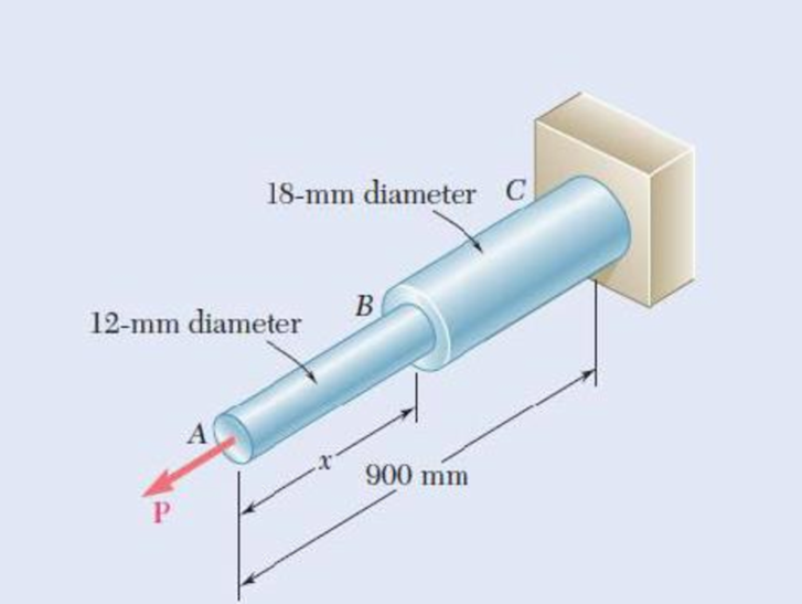
Fig. P11.15
(a)
Find the factor of safety with respect to permanent deformation when
Answer to Problem 15P
The factor of safety with respect to permanent deformation is
Explanation of Solution
Given information:
The diameter of the steel rod AB is
The diameter of the steel rod BC is
The length of the rod AB is
The length of the rod BC is
The modulus of elasticity of the steel is
The yield strength of steel is
The strain energy acquired by the assembly is
Calculation:
Calculate the area of the rod (A) as shown below.
For the steel rod AB.
Substitute
For the steel rod BC.
Substitute
Hence, the minimum area of the rod
Calculate the load
Substitute
Calculate the strain energy
Calculate the strain energy for rod ABC as shown below.
Substitute
Calculate the factor of safety
Substitute
Therefore, the factor of safety with respect to permanent deformation is
(b)
Find the factor of safety with respect to permanent deformation when
Answer to Problem 15P
The factor of safety with respect to permanent deformation is
Explanation of Solution
Given information:
The diameter of the steel rod AB is
The diameter of the steel rod BC is
The length of the rod AB is
The length of the rod BC is
The modulus of elasticity of the steel is
The yield strength of steel is
The strain energy acquired by the assembly is
Calculation:
Refer to part (a).
The area of the steel rod AB is
The area of the steel rod BC is
The load acting on the assembly is
Calculate the strain energy
Substitute
Calculate the factor of safety
Substitute
Therefore, the factor of safety with respect to permanent deformation is
Want to see more full solutions like this?
Chapter 11 Solutions
Mechanics of Materials, 7th Edition


- An aluminum plate (E= 74 GPa, ν= 0.33) is subjected to a centric axial load that causes a normal stress σ. Knowing that, before loading, a line of slope 2:1 is scribed on the plate, determine the slope of the line when σ=125 MPa.arrow_forward3) An eccentric force P is applied as shown in Fig. 2 to a steel bar of 25 x 90-mm cross section. The strains at A and B have been measured and found to be ƐA = + 400µ and be ЄB = - - 90μ. Knowing that E = 210 GPa, determine (a) the magnitude of force P, (b) the distance d, and (c) neatly draw the stress distribution diagrams of the system. 30 mm 25 mm- 90 mm A B Fig. 2 1 45 mm 15 mmarrow_forwardTwo gage marks are placed exactly 250mm apart on a 12mm-diameter aluminum rod with E=73Gpa and an ultimate strength of 140Mpa. Knowing that the distance between the gage marks is 250.28mm after a load is applied, determine (a) the stress in the rod, (b) the factor of safety.arrow_forward
- In a standard tensile test, a steel rod of 22-mm diameter is subjected to a tension force of 75 kN. Knowing that ν=0.30 and E=200 GPa, determine (a) the elongation of the rod in a 200-mm gage length, (b) the change in diameter of the rodarrow_forwardTwo gage marks are placed exactly 250 mm apart on a 12-mm-diameter aluminum rod with E = 73 GPa and an ultimate strength of 140 MPa. Knowing that the distance between the gage marks is 250.28 mm after a load is applied, determine the stress in the rodarrow_forwardA 2.75-kN tensile load is applied to a test coupon made from 1.6-mm flat steel plate (E=200 GPa, ν= 0.30). Determine the resulting change (a) in the 50-mm gage length, (b) in the width of portion ABof the test coupon, (c) in the thickness of portion AB, (d)in the cross-sectional area of portion AB.arrow_forward
- A 9 kN tensile load will be applied to a 50 m length of steel wire with E=200 GPa. Knowing that the normal stress must not exceed 150 MPa and that the increase in the length of the wire should be at most 25 mm, determine the smallest diameter wire which can be used.arrow_forwardIn a standard tensile test, a steel rod of 25 mm diameter and 200 mm long exhibits a strain of 1.0186x 10³ upon application of an axial load of 220 kN. Knowing that v = 0.4 and E = 200 GPa, determine the change in diameter of the rod. Answer in millimeters.arrow_forwardTwo wooden members of uniform rectangular cross section of sides a = 100 mm and b = 60 mm are joined by a simple glued joint as shown. Knowing that the ultimate stresses for the joint are σU =1.26 MPa in tension and τU = 1.50 MPa in shear and that P =6 kN, determine the factor of safety for the joint when (a) α =20°,(b) α =35°, (c) α =45°. For each of these values of α, also determine whether the joint will fail in tension or in shear if P is increased until rupture occurs.arrow_forward
- A fabric used in air-inflated structures is subjected to a biaxial load-ing that results in normal stresses σx=120 MPa and σz =160 MPa. Knowing that the properties of the fabric can be approximated as E=87 GPa and ν= 0.34, determine the change in length of (a) side AB, (b) side BC, (c) diagonal AC.arrow_forwardA 12-kN tensile load will be applied to a 50-m length of steel wire with E= 200 GPa. Determine the smallest diameter wire that can be used, knowing that the normal stress must not exceed 150 MPa and that the increase in length of the wire must not exceed 25 mm. The smallest diameter that can be used is mm.arrow_forward! Required information Both portions of the rod ABC are made of an aluminum for which E= 70 GPa. Given: P = 5 kN. 0.4 m 0.5 m 20-mm diameter 60-mm diameter Determine the deformation of B. The deformation of Bis [ mm ↓.arrow_forward
 Elements Of ElectromagneticsMechanical EngineeringISBN:9780190698614Author:Sadiku, Matthew N. O.Publisher:Oxford University Press
 Mechanics of Materials (10th Edition)Mechanical EngineeringISBN:9780134319650Author:Russell C. HibbelerPublisher:PEARSON
 Thermodynamics: An Engineering ApproachMechanical EngineeringISBN:9781259822674Author:Yunus A. Cengel Dr., Michael A. BolesPublisher:McGraw-Hill Education
 Control Systems EngineeringMechanical EngineeringISBN:9781118170519Author:Norman S. NisePublisher:WILEY
 Mechanics of Materials (MindTap Course List)Mechanical EngineeringISBN:9781337093347Author:Barry J. Goodno, James M. GerePublisher:Cengage Learning
 Engineering Mechanics: StaticsMechanical EngineeringISBN:9781118807330Author:James L. Meriam, L. G. Kraige, J. N. BoltonPublisher:WILEY