
Fundamentals of Electric Circuits
6th Edition
ISBN: 9780078028229
Author: Charles K Alexander, Matthew Sadiku
Publisher: McGraw-Hill Education
expand_more
expand_more
format_list_bulleted
Videos
Textbook Question
Chapter 8, Problem 82CP
The circuit in Fig. 8.123 is the electrical analog of body functions used in medical schools to study convulsions. The analog is as follows:
C1 = Volume of fluid in a drug
C2 = Volume of blood stream in a specified region
R1 = Resistance in the passage of the drug from the input to the blood stream
R2 = Resistance of the excretion
v0 = Initial concentration of the drug dosage
v(t) = Percentage of the drug in the blood stream
Find v(t) for t > 0 given that C1 = 0.5 μF, C2 = 5 μF, R1 = 5 MΩ, R2 = 2.5 MΩ, and v0 = 60u(t) V.
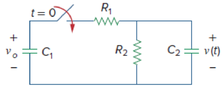
Figure 8.123
For Prob. 8.82.
Expert Solution & Answer
Want to see the full answer?
Check out a sample textbook solution
Students have asked these similar questions
Stability of a control system
Design a system that has a 15% overshoot and
stabilizes in 2 seconds. analyzes its absolute
stability analyzes its relative stability if a zero is
added to it at +3
A historic bridge shows a deterioration in its structure. It will be restricted for vehicles weighing less than 1600 kg; otherwise it will be prevented access through a “feather” type barrier. To monitor the weight of the car are used 4 independent sensors placed on a platform just below the tires of the vehicle. Each sensor emits 1mV for every Kg. The weight of the car is the sum of the four sensors. Design a circuit that displays the weight of the car on a digital multimeter.
17
Answer:
C +
There are two questions, first about an ideal diode and then about a modeled diode. For the modeled diode, the voltage across its terminals is 0.7V when it is "on".
Which of the following statements are true about the ideal diode above?
a. If v 0, then the diode can be replaced by an independent current source.
f. If v<0, then the diode can be replaced by an independent current source.
g. None of these statements is true.
Enter a single string of letters, in alphabetical order ("abcdef").
Chapter 8 Solutions
Fundamentals of Electric Circuits
Ch. 8.2 - The switch in Fig. 8.4 was open for a long time...Ch. 8.2 - For the circuit in Fig. 8.7, find: (a) iL(0+),...Ch. 8.3 - If R = 10 , L = 5 H, and C = 2 mF in Fig. 8.8,...Ch. 8.3 - The circuit in Fig. 8.12 has reached steady state...Ch. 8.4 - In Fig. 8.13, let R = 2 , L = 0.4 H, C = 25 mF,...Ch. 8.4 - Refer to the circuit in Fig. 8.17. Find v(t) for t...Ch. 8.5 - Having been in position a for a long time, the...Ch. 8.6 - Find i(t) and v(t) for t 0 in the circuit of Fig....Ch. 8.7 - Determine v and i for t 0 in the circuit of Fig....Ch. 8.7 - For t 0, obtain v0(t) in the circuit of Fig....
Ch. 8.8 - In the op amp circuit shown in Fig. 8.34, vs =...Ch. 8.9 - Find i(t) using PSpice for 0 t 4 s if the pulse...Ch. 8.9 - Refer to the circuit in Fig. 8.21 (see Practice...Ch. 8.10 - Draw the dual circuit of the one in Fig. 8.46.Ch. 8.10 - For the circuit in Fig. 8.50, obtain the dual...Ch. 8.11 - In Fig. 8.52, find the capacitor voltage vC for t ...Ch. 8.11 - The output of a D/A converter is shown in Fig....Ch. 8 - For the circuit in Fig. 8.58, the capacitor...Ch. 8 - For Review Questions 8.1 and 8.2. 8.2For the...Ch. 8 - When a step input is applied to a second-order...Ch. 8 - If the roots of the characteristic equation of an...Ch. 8 - In a series RLC circuit, setting R = 0 will...Ch. 8 - Prob. 6RQCh. 8 - Refer to the series RLC circuit in Fig. 8.59. What...Ch. 8 - Consider the parallel RLC circuit in Fig. 8.60....Ch. 8 - Match the circuits in Fig. 8.61 with the following...Ch. 8 - Prob. 10RQCh. 8 - For the circuit in Fig. 8.62, find: (a)i(0+) and...Ch. 8 - Using Fig. 8.63, design a problem to help other...Ch. 8 - Refer to the circuit shown in Fig. 8.64....Ch. 8 - In the circuit of Fig. 8.65, find: (a) v(0+) and...Ch. 8 - Refer to the circuit in Fig. 8.66. Determine: (a)...Ch. 8 - In the circuit of Fig. 8.67, find: (a) vR(0+) and...Ch. 8 - A series RLC circuit has R = 20 k, L = 0.2 mH, and...Ch. 8 - Design a problem to help other students better...Ch. 8 - The current in an RLC circuit is described by...Ch. 8 - The differential equation that describes the...Ch. 8 - Prob. 11PCh. 8 - If R = 50 , L = 1.5 H, what value of C will make...Ch. 8 - For the circuit in Fig. 8.68, calculate the value...Ch. 8 - The switch in Fig. 8.69 moves from position A to...Ch. 8 - The responses of a series RLC circuit are...Ch. 8 - Find i(t) for t 0 in the circuit of Fig. 8.70....Ch. 8 - In the circuit of Fig. 8.71, the switch...Ch. 8 - Find the voltage across the capacitor as a...Ch. 8 - Obtain v(t) for t 0 in the circuit of Fig. 8.73....Ch. 8 - The switch in the circuit of Fig. 8.74 has been...Ch. 8 - Calculate v(t) for t 0 in the circuit of Fig....Ch. 8 - Assuming R = 2 k, design a parallel RLC circuit...Ch. 8 - For the network in Fig. 8.76, what value of C is...Ch. 8 - The switch in Fig. 8.77 moves from position A to...Ch. 8 - Using Fig. 8.78, design a problem to help other...Ch. 8 - The step response of an RLC circuit is given by...Ch. 8 - Prob. 27PCh. 8 - A series RLC circuit is described by...Ch. 8 - Solve the following differential equations subject...Ch. 8 - Prob. 30PCh. 8 - Consider the circuit in Fig. 8.79. Find vL(0+) and...Ch. 8 - For the circuit in Fig. 8.80, find v(t) for t 0.Ch. 8 - Find v(t) for t 0 in the circuit of Fig. 8.81.Ch. 8 - Calculate i(t) for t 0 in the circuit of Fig....Ch. 8 - Using Fig. 8.83, design a problem to help other...Ch. 8 - Obtain v(t) and i(t) for t 0 in the circuit of...Ch. 8 - For the network in Fig. 8.85, solve for i(t) for t...Ch. 8 - Refer to the circuit in Fig. 8.86. Calculate i(t)...Ch. 8 - Determine v(t) for t 0 in the circuit of Fig....Ch. 8 - The switch in the circuit of Fig. 8.88 is moved...Ch. 8 - For the network in Fig. 8.89, find i(t) for t 0....Ch. 8 - Given the network in Fig. 8.90, find v(t) for t ...Ch. 8 - The switch in Fig. 8.91 is opened at t = 0 after...Ch. 8 - A series RLC circuit has the following parameters:...Ch. 8 - In the circuit of Fig. 8.92, find v(t) and i(t)...Ch. 8 - Prob. 46PCh. 8 - Find the output voltage vo(t) in the circuit of...Ch. 8 - Given the circuit in Fig. 8.95, find i(t) and v(t)...Ch. 8 - Determine i(t) for t 0 in the circuit of Fig....Ch. 8 - For the circuit in Fig. 8.97, find i(t) for t 0....Ch. 8 - Find v(t) for t 0 in the circuit of Fig. 8.98....Ch. 8 - The step response of a parallel RLC circuit is...Ch. 8 - After being open for a day, the switch in the...Ch. 8 - Using Fig. 8.100, design a problem to help other...Ch. 8 - For the circuit in Fig. 8.101, find v(t) for t 0....Ch. 8 - In the circuit of Fig. 8.102, find i(t) for t 0....Ch. 8 - Given the circuit shown in Fig. 8.103, determine...Ch. 8 - In the circuit of Fig. 8.104, the switch has been...Ch. 8 - The switch in Fig. 8.105 has been in position 1...Ch. 8 - Obtain i1 and i2 for t 0 in the circuit of Fig....Ch. 8 - For the circuit in Prob. 8.5, find i and v for t ...Ch. 8 - Find the response vR(t) for t 0 in the circuit of...Ch. 8 - For the op amp circuit in Fig. 8.108, find the...Ch. 8 - Using Fig. 8.109, design a problem to help other...Ch. 8 - Determine the differential equation for the op amp...Ch. 8 - Obtain the differential equations for vo(t) in the...Ch. 8 - In the op amp circuit of Fig. 8.112, determine...Ch. 8 - For the step function vs = u(t), use PSpice or...Ch. 8 - Given the source-free circuit in Fig. 8.114, use...Ch. 8 - For the circuit in Fig. 8.115, use PSpice or...Ch. 8 - Obtain v(t) for 0 t 4 s in the circuit of Fig....Ch. 8 - The switch in Fig. 8.117 has been in position 1...Ch. 8 - Design a problem, to be solved using PSpice or...Ch. 8 - Draw the dual of the circuit shown in Fig. 8.118.Ch. 8 - Obtain the dual of the circuit in Fig. 8.119.Ch. 8 - Find the dual of the circuii in Fig. 8.120.Ch. 8 - Draw the dual of the circuit in Fig. 8.121.Ch. 8 - An automobile airbag igniter is modeled by the...Ch. 8 - A load is modeled as a 100-mH inductor in parallel...Ch. 8 - A mechanical system is modeled by a series RLC...Ch. 8 - An oscillogram can be adequately modeled by a...Ch. 8 - The circuit in Fig. 8.123 is the electrical analog...Ch. 8 - Figure 8.124 shows a typical tunnel-diode...
Knowledge Booster


Learn more about
Need a deep-dive on the concept behind this application? Look no further. Learn more about this topic, electrical-engineering and related others by exploring similar questions and additional content below.Similar questions
- Electrical Engineering a. Which operation(s) should be applied to the Image A below to obtain the Image B? Why? Image A Image Barrow_forward30 45 N 50 E A B D N 45 30 N 50 E 2. 100 m (a) Figure 8.44 N 40W N 40 Warrow_forwardCompanies designs, creates, and sells Integrated Circuits (chips). What do your buyers useto compare your IC products against your competition’s? Give 3 types of IC benchmarkmeasurements in short answerarrow_forward
- A power suppply having 220 V AC input and two fixed outputs as 10 V DC and 20 V DC is requested from you. For this purpose, a transformer with 220 V AC input / 15 V AC output, some capacitors, some silicon diodes, and zener diodes are presented. a) Design your power supply and point out DC voltage outputs b) Explain the operation of the network and all the components used in the design c) Calculate and plot input and output signals of the network Hint: For design, remember clipper, clamper, rectifier,voltage multiplier and zener circuitsarrow_forwardA basic D’Arsonval movement with a full-scale deflection of 50μA and internal resistance of 500Ω is used as a DC voltmeter. Determine the value of the multiplier resistance needed to measure a voltage range of 0-10V and its sensitivity (S). [Ans. 199.5kΩ, 20kΩ/V]arrow_forwardElectrical engineering A mesh collider a) is as accurate as the triangle count on the mesh b)is the variable optiom for complex meshes such as player characters c)is the only way to get headshots to work d)is faster than a box colliderarrow_forward
- Note: Don't use chatGPT or google or any other source to copy paste. I will dislike the solution if you do so.I need unique solution. if you are not able to solve please let other expert review. The given diagram represents a sequential circuit. This circuit has a single input labeled "x" and a single output labeled "Z." It also has two state variables called Q1 and Q2, which together can have four different combinations of present states: 00, 01, 10, and 11.Create the state table and state diagramand boolean equation as well.arrow_forwardThe figure below shows a circuit with an open switch, an emf device, E= 33 V, and a resistor, R = 48 Q. If we assume the switch remains open, use the given values to find the potential difference between the following points. (a) a Vb - V₂ (b) Vc-Vo V (c) Va-Vc (d) V-V 1+ b Rarrow_forwardIn the given circuit, find (a) the current through the 8.0ohm resistor and (b) the total rate of dissipation of electrical energy in the 8-ohm resistor and in the internal resistance of the batteries. (c) What is the rate of production of electrical energy and (d) the rate of consumption of electrical energy?arrow_forward
- + % t=0 C₁ R₁ ww R₂ S The value of (t) for t> 0 is C₂ v(t) The circuit in the given figure is the electrical analog of body functions used in medical schools to study convulsions. The analog is as follows: C₁ = Volume of fluid in a drug C2 = Volume of blood stream in a specified region R₁ = Resistance in the passage of the drug from the input to the blood stream R2 = Resistance of the excretion mechanism, such as kidney, etc. Vo = Initial concentration of the drug dosage ✓(t) = Percentage of the drug in the blood stream Find (t) for t> 0 given that C₁ = 0.5 μF, C₂ = 5 μF, R₁ = 5 MQ, R₂ = 2.6 MQ, and vo = 60 u(t) V. |(1-e-2.9t/25) V.arrow_forwardYour team is building a robot that is powered with a 35Ah battery. During testing, the robot will run for a maximum of 5 hours before running out of battery, interrupting testing. The team would like to have a better idea of when the robot is going to run out of battery and needs to be recharged. An electrical engineer on your team designs a board to help solve this, with an LTC2944 and a 0.3mohm sense resistor. You are tasked with writing the software to read the accumulated battery discharge, in mAh, at the highest resolution possible. What should register bits B[5:3] be set to, in hexadecimal (please omit ‘0x’ from your answer)? Look up the datasheet to answer this question.arrow_forwardIn measuring a voltage, a voltimeter uses some current from the circuit. Consequently, the voltage measured is only an approximation to the voltage present when the voltmeter is not connected. Consider a circuit consisting of two 3000-Ω resistors connected in series across a 60.0-V battery. A non-digital voltmeter has a full-scale voltage of 60.0 V and uses a galvanometer with a full-scale deflection of 5.00 mA. What is the difference (VA - VB) between A) the voltage across one of the two resistors and B) the voltage that this voltmeter registers when it is connected across one of the two resistors?arrow_forward
arrow_back_ios
SEE MORE QUESTIONS
arrow_forward_ios
Recommended textbooks for you
 Introductory Circuit Analysis (13th Edition)Electrical EngineeringISBN:9780133923605Author:Robert L. BoylestadPublisher:PEARSON
 Delmar's Standard Textbook Of ElectricityElectrical EngineeringISBN:9781337900348Author:Stephen L. HermanPublisher:Cengage Learning
 Programmable Logic ControllersElectrical EngineeringISBN:9780073373843Author:Frank D. PetruzellaPublisher:McGraw-Hill Education
 Fundamentals of Electric CircuitsElectrical EngineeringISBN:9780078028229Author:Charles K Alexander, Matthew SadikuPublisher:McGraw-Hill Education
 Electric Circuits. (11th Edition)Electrical EngineeringISBN:9780134746968Author:James W. Nilsson, Susan RiedelPublisher:PEARSON
 Engineering ElectromagneticsElectrical EngineeringISBN:9780078028151Author:Hayt, William H. (william Hart), Jr, BUCK, John A.Publisher:Mcgraw-hill Education,
Introductory Circuit Analysis (13th Edition)
Electrical Engineering
ISBN:9780133923605
Author:Robert L. Boylestad
Publisher:PEARSON
Delmar's Standard Textbook Of Electricity
Electrical Engineering
ISBN:9781337900348
Author:Stephen L. Herman
Publisher:Cengage Learning
Programmable Logic Controllers
Electrical Engineering
ISBN:9780073373843
Author:Frank D. Petruzella
Publisher:McGraw-Hill Education
Fundamentals of Electric Circuits
Electrical Engineering
ISBN:9780078028229
Author:Charles K Alexander, Matthew Sadiku
Publisher:McGraw-Hill Education
Electric Circuits. (11th Edition)
Electrical Engineering
ISBN:9780134746968
Author:James W. Nilsson, Susan Riedel
Publisher:PEARSON
Engineering Electromagnetics
Electrical Engineering
ISBN:9780078028151
Author:Hayt, William H. (william Hart), Jr, BUCK, John A.
Publisher:Mcgraw-hill Education,
Systems and Simulation - Lecture 3: Modelling of Mechanical systems; Author: bioMechatronics Lab;https://www.youtube.com/watch?v=fMcDdyoC9mA;License: Standard Youtube License