
Engineering Mechanics: Statics & Dynamics (14th Edition)
14th Edition
ISBN: 9780133915426
Author: Russell C. Hibbeler
Publisher: PEARSON
expand_more
expand_more
format_list_bulleted
Concept explainers
Videos
Textbook Question
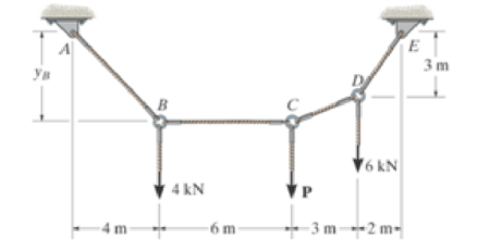
Chapter 7.4, Problem 101P
Determine the force P needed to hold the cable in the position shown, i.e., so segment BC remains horizontal. Also, compute the sag yB sand the maximum tension in the cable.
Prob. 7–101
Expert Solution & Answer
Want to see the full answer?
Check out a sample textbook solution
Students have asked these similar questions
The 440-kg uniform beam is subjected to the three external loads shown. Compute the reactions at the
support point O. The x-y plane is vertical. Positive values are to the right, up, and counterclockwise.
y
41 kN-m
B
HÖZ
4.8 KN
1.7 m
1.1 m
Answers:
Ox=
Oy= i
Mo= i
i
A
kN
kN
1.7 m
kN.m
27
2.7 KN
x
The
520-kg uniform beam is subjected to the three external loads shown. Compute the reactions at the support point O. The x-y plane
is vertical. Positive values are to the right, up, and counterclockwise.
13 kN-m
23
3.0 KN
B
x
C
1.1 m
Answers:
Ox
= i
Oy=
i
Mo=
i
3.9 KN
1.6 m
KN
KN
1.6 m
kN.m
The beam is loaded with a uniformly varying load 0 at point D and maximum of 7 kN/m at the fixed support.
Determine the tension in the cable.
D
B
0.8 m
1.8 m
0.4 m
25 kN
Chapter 7 Solutions
Engineering Mechanics: Statics & Dynamics (14th Edition)
Ch. 7.1 - In each case, calculate the reaction at A and then...Ch. 7.1 - Determine the normal force, shear force, and...Ch. 7.1 - Determine the normal force, shear force, and...Ch. 7.1 - Determine the normal force, shear force, and...Ch. 7.1 - Determine the normal force, shear force, and...Ch. 7.1 - Determine the normal force, shear force, and...Ch. 7.1 - Determine the normal force, shear force, and...Ch. 7.1 - Determine the shear force and moment at points C...Ch. 7.1 - Determine the internal normal force and shear...Ch. 7.1 - Two beams are attached to the column such that...
Ch. 7.1 - The beam weighs 280 lb/ft. Determine the internal...Ch. 7.1 - The pliers are used to grip the tube at B. If a...Ch. 7.1 - Determine the distance a as a fraction of the...Ch. 7.1 - Determine the internal shear force and moment...Ch. 7.1 - Determine the internal shear force and moment...Ch. 7.1 - Determine the normal force, shear force, and...Ch. 7.1 - The cable will fail when subjected to a tension of...Ch. 7.1 - Determine the internal normal force, shear force,...Ch. 7.1 - Determine the distance a between the bearings in...Ch. 7.1 - Determine the internal normal force, shear force,...Ch. 7.1 - The shaft is supported by a journal bearing at A...Ch. 7.1 - Determine the internal normal force, shear force,...Ch. 7.1 - Determine the internal normal force, shear force,...Ch. 7.1 - The cantilevered rack is used to support each end...Ch. 7.1 - Determine the internal normal force, shear force,...Ch. 7.1 - Determine the internal normal force, shear force,...Ch. 7.1 - Rod AB is fixed to a smooth collar D, which slides...Ch. 7.1 - Determine the internal normal force, shear force,...Ch. 7.1 - Determine the internal normal force, shear force,...Ch. 7.1 - Determine the internal normal force, shear force,...Ch. 7.1 - Determine the ratio of a/b for which the shear...Ch. 7.1 - Determine the normal force, shear force, and...Ch. 7.1 - Determine the internal normal force, shear force,...Ch. 7.1 - Determine the internal normal force, shear force,...Ch. 7.1 - Determine the internal normal force, shear force,...Ch. 7.1 - Determine the normal force, shear force, and...Ch. 7.1 - Determine the normal force, shear force, and...Ch. 7.1 - Determine the internal normal force, shear force,...Ch. 7.1 - Determine the internal normal force, shear force,...Ch. 7.1 - Determine the internal normal force, shear force,...Ch. 7.1 - Determine the internal normal force, shear force,...Ch. 7.1 - The strongback or lifting beam is used for...Ch. 7.1 - Determine the internal normal force, shear force,...Ch. 7.1 - Determine the internal normal force, shear force,...Ch. 7.1 - Determine the internal normal force, shear force,...Ch. 7.1 - The distributed loading W = W0 sin , measured per...Ch. 7.1 - Solve Prob. 7-39 for = 120. Probs. 739/40Ch. 7.1 - Determine the x, y. z components of force and...Ch. 7.1 - Determine the x, y, z components of force and...Ch. 7.1 - Determine the x, y, z components of internal...Ch. 7.1 - Determine the x, y. z components of internal...Ch. 7.2 - Determine the shear and moment as a function of x,...Ch. 7.2 - Determine the shear and moment as a function of x,...Ch. 7.2 - Determine the shear and moment as a function of x,...Ch. 7.2 - Determine the shear and moment as a function of x,...Ch. 7.2 - Determine the shear and moment as a function of x,...Ch. 7.2 - Determine the shear and moment as a function of x,...Ch. 7.2 - Draw the shear and moment diagrams for the shaft...Ch. 7.2 - Draw the shear and moment diagrams for the beam...Ch. 7.2 - Draw the shear and moment diagrams for the beam...Ch. 7.2 - Draw the shear and moment diagrams for the...Ch. 7.2 - Draw the shear and moment diagrams of the beam (a)...Ch. 7.2 - If L = 9 m, the beam will fail when the maximum...Ch. 7.2 - Draw the shear and moment diagrams for the beam....Ch. 7.2 - Draw the shear and moment diagrams for the beam....Ch. 7.2 - Draw the shear and bending-moment diagrams for the...Ch. 7.2 - The shaft is supported by a smooth thrust bearing...Ch. 7.2 - Draw the shear and moment diagrams for the beam....Ch. 7.2 - Draw the shear and moment diagrams for the beam....Ch. 7.2 - Draw the shear and moment diagrams for the...Ch. 7.2 - Draw the shear and bending-moment diagrams for...Ch. 7.2 - Draw the shear and moment diagrams for the beam....Ch. 7.2 - The shaft is supported by a smooth thrust bearing...Ch. 7.2 - Draw the shear and moment diagrams for the beam....Ch. 7.2 - The beam will fail when the maximum internal...Ch. 7.2 - Prob. 63PCh. 7.2 - Prob. 64PCh. 7.2 - Prob. 65PCh. 7.2 - Draw the shear and moment diagrams for the beam....Ch. 7.2 - Determine the internal normal force, shear force,...Ch. 7.2 - The quarter circular rod lies in the horizontal...Ch. 7.2 - Express the internal shear and moment components...Ch. 7.3 - Draw the shear and moment diagrams for the beam....Ch. 7.3 - Draw the shear and moment diagrams for the beam....Ch. 7.3 - Draw the shear and moment diagrams for the beam....Ch. 7.3 - Draw the shear and moment diagrams for the beam....Ch. 7.3 - Draw the shear and moment diagrams for the beam....Ch. 7.3 - Draw the shear and moment diagrams for the beam....Ch. 7.3 - Draw the shear and moment diagrams for the beam....Ch. 7.3 - Draw the shear and moment diagrams for the beam....Ch. 7.3 - Draw the shear and moment diagrams for the beam....Ch. 7.3 - Draw the shear and moment diagrams for the...Ch. 7.3 - Draw the shear and moment diagrams for the beam....Ch. 7.3 - Draw the shear and moment diagrams for the beam....Ch. 7.3 - Draw the shear and moment diagrams for the beam....Ch. 7.3 - Draw the shear and moment diagrams for the beam....Ch. 7.3 - Draw the shear and moment diagrams for the beam....Ch. 7.3 - Draw the shear and moment diagrams for the shaft....Ch. 7.3 - Draw the shear and moment diagrams for the beam....Ch. 7.3 - The beam consists of three segments pin connected...Ch. 7.3 - Draw the shear and moment diagrams for the beam....Ch. 7.3 - Draw the shear and moment diagrams for the beam....Ch. 7.3 - Draw the shear and moment diagrams for the beam....Ch. 7.3 - Draw the shear and moment diagrams for the beam....Ch. 7.3 - Draw the shear and moment diagrams for the beam....Ch. 7.3 - Draw the shear and moment diagrams for the beam....Ch. 7.3 - Draw the shear and moment diagrams for the beam....Ch. 7.3 - Draw the shear and moment diagrams for the beam....Ch. 7.3 - Draw the shear and moment diagrams for the beam....Ch. 7.3 - Draw the shear and moment diagrams for the beam....Ch. 7.3 - Draw the shear and moment diagrams for the beam....Ch. 7.3 - Draw the shear and moment diagrams for the beam....Ch. 7.4 - The cable supports the three loads shown....Ch. 7.4 - Prob. 95PCh. 7.4 - Determine the tension in each segment of the cable...Ch. 7.4 - Prob. 97PCh. 7.4 - The cable supports the loading shown. Determine...Ch. 7.4 - The cable supports the three loads shown....Ch. 7.4 - The cable supports the three loads shown....Ch. 7.4 - Determine the force P needed to hold the cable in...Ch. 7.4 - Determine the maximum uniform loading w, measured...Ch. 7.4 - The cable is subjected to a uniform loading of w =...Ch. 7.4 - The cable AB is subjected to a uniform loading of...Ch. 7.4 - If x = 2 ft and the crate weighs 300 lb, which...Ch. 7.4 - If yB = 1.5 ft. determine the largest weight of...Ch. 7.4 - The cable supports a girder which weighs 850...Ch. 7.4 - The cable is subjected to a uniform loading of w =...Ch. 7.4 - If the pipe has a mass per unit length of 1500...Ch. 7.4 - Prob. 110PCh. 7.4 - Prob. 111PCh. 7.4 - The cable will break when the maximum tension...Ch. 7.4 - Prob. 113PCh. 7.4 - The power transmission cable weighs 10 lb/fl. If...Ch. 7.4 - Prob. 115PCh. 7.4 - Prob. 116PCh. 7.4 - Prob. 117PCh. 7.4 - Prob. 118PCh. 7.4 - Show that the deflection curve of the cable...Ch. 7.4 - Prob. 120PCh. 7.4 - Prob. 121PCh. 7.4 - Prob. 122PCh. 7.4 - A cable has a weight of 5 lb/ft. If it can span...Ch. 7.4 - The 10 kg/m cable is suspended between the...Ch. 7.4 - Determine the internal normal force, shear force,...Ch. 7.4 - Prob. 2RPCh. 7.4 - Prob. 3RPCh. 7.4 - Prob. 4RPCh. 7.4 - Draw the shear and moment diagrams for the beam....Ch. 7.4 - A chain is suspended between points at the same...
Knowledge Booster


Learn more about
Need a deep-dive on the concept behind this application? Look no further. Learn more about this topic, mechanical-engineering and related others by exploring similar questions and additional content below.Similar questions
- The 530-kg uniform beam is subjected to the three external loads shown. Compute the reactions at the support point O. The x-y plane is vertical. Positive values are to the right, up, and counterclockwise. y 36 kN-m 24 3.8 kN A B - - 2.7 kN - 1.0 m 1.7 m 1.7 m Answers: Ox i kN Oy= kN Mo = i kN-marrow_forwardThe cable supports a girder which weighs 850 lb/ft. Determine the tension in the cable at points A, B, and C. -100 ft- 40 ft 20 ft At point B, take x=0 and y=0 (origin point). So, Which following one is TRUE?arrow_forwardProblem 4 The cable of a suspension bridge supports half of the uniform road surface between the two towers at A and B, Fig. 7-21a. If this distributed loading is 0,, determine the maximum force developed in the cable and the cable's required length. The span L and sag h are known.arrow_forward
- The 460-kg uniform beam is subjected to the three external loads shown. Compute the reactions at the support point O. The x-y plane is vertical. Positive values are to the right, up, and counterclockwise. 0 1.2 m Answers: Ox Oy = i Mo= i i A 6.1 KN 1.6 m 19 kN.m B kN kN 1.6 m kN-m 20 C 2.7 KN -1xarrow_forwardThe shaft assembly is supported by two smooth journal bearings A and B and a short link DC. If a couple moment is shown, components of force reaction at the journal bearings and 20 120 mm applied to the shaft as determine the the force in the link. The link lies 250 mm 300 mm in a plane parallel to the y-z plane and the bearings are properly aligned on the shaft. 250 N m 400 mmarrow_forwardThe slope of the 4.3 kN force F is specified as shown in the figure. Express F as a vector in terms of the unit vectors i and j. Assume a 13, b = 6. Answer: F = ( i a i+ j) KNarrow_forward
- Example The man has a weight W and stands at the center of the plank. II the planes at A and B are smooth, determine the tension in the cord in terms of W and 6. W RB NB (L/2)cos (L/2)cos d NAarrow_forwardThe 400-kg uniform beam is subjected to the three external loads shown. Compute the reactions at the support point 0. The x-y plane is vertical. Positive values are to the right, up, and counterclockwise. y 33 4.2 kN 43 kN-m A B 2.7 kN - 1.2 m-- 1.7 m 1.7 m Answers: Ox- i kN Oy = i kN Mo= i kN-marrow_forwardThe 500-kg uniform beam is subjected to the three external loads shown. Compute the reactions at the support point O. The x-y plane is vertical. Positive values are to the right, up, and counterclockwise. 13 kN m 29 2.9 kN - - x 6.4 kN - 1.3 m- 1.9 m 1.9 m Answers: Ox = kN Oy= kN Mo = kN-marrow_forward
- The 570-kg uniform beam is subjected to the three external loads shown. Compute the reactions at the support point O. The x-y plane is vertical. Positive values are to the right, up, and counterclockwise. y 0 Answers: Ox= Oy= = Mo = 1.2 m 1.7 m Mi i A F 5.1 KN 44 kN-m B 1.7 m KN kN kN-m 35 10 C 3.4 KN - xarrow_forwardThe 300 kg uniform I-beam supports the 120 kg load. What are the reactions at the supports A and B? 5.6 m - 2.4 m B A 120 kgarrow_forwardFor the curved beam, determine the horizontal and vertical components of force at pin A and vertical reaction at the rocker B. Neglect the weight of the beam. 500 N 200 N 10% 15% 2m Barrow_forward
arrow_back_ios
SEE MORE QUESTIONS
arrow_forward_ios
Recommended textbooks for you
 Elements Of ElectromagneticsMechanical EngineeringISBN:9780190698614Author:Sadiku, Matthew N. O.Publisher:Oxford University Press
 Mechanics of Materials (10th Edition)Mechanical EngineeringISBN:9780134319650Author:Russell C. HibbelerPublisher:PEARSON
 Thermodynamics: An Engineering ApproachMechanical EngineeringISBN:9781259822674Author:Yunus A. Cengel Dr., Michael A. BolesPublisher:McGraw-Hill Education
 Control Systems EngineeringMechanical EngineeringISBN:9781118170519Author:Norman S. NisePublisher:WILEY
 Mechanics of Materials (MindTap Course List)Mechanical EngineeringISBN:9781337093347Author:Barry J. Goodno, James M. GerePublisher:Cengage Learning
 Engineering Mechanics: StaticsMechanical EngineeringISBN:9781118807330Author:James L. Meriam, L. G. Kraige, J. N. BoltonPublisher:WILEY
Elements Of Electromagnetics
Mechanical Engineering
ISBN:9780190698614
Author:Sadiku, Matthew N. O.
Publisher:Oxford University Press
Mechanics of Materials (10th Edition)
Mechanical Engineering
ISBN:9780134319650
Author:Russell C. Hibbeler
Publisher:PEARSON
Thermodynamics: An Engineering Approach
Mechanical Engineering
ISBN:9781259822674
Author:Yunus A. Cengel Dr., Michael A. Boles
Publisher:McGraw-Hill Education
Control Systems Engineering
Mechanical Engineering
ISBN:9781118170519
Author:Norman S. Nise
Publisher:WILEY
Mechanics of Materials (MindTap Course List)
Mechanical Engineering
ISBN:9781337093347
Author:Barry J. Goodno, James M. Gere
Publisher:Cengage Learning
Engineering Mechanics: Statics
Mechanical Engineering
ISBN:9781118807330
Author:James L. Meriam, L. G. Kraige, J. N. Bolton
Publisher:WILEY
EVERYTHING on Axial Loading Normal Stress in 10 MINUTES - Mechanics of Materials; Author: Less Boring Lectures;https://www.youtube.com/watch?v=jQ-fNqZWrNg;License: Standard YouTube License, CC-BY