
Mechanics of Materials
9th Edition
ISBN: 9780133254426
Author: Russell C. Hibbeler
Publisher: Prentice Hall
expand_more
expand_more
format_list_bulleted
Videos
Textbook Question
Chapter 7.3, Problem 7.40P
The simply supported beam is built up from three boards by nailing them together as shown. The wood has an allowable shear stress of τallow = 1.5 MPa, and an allowable bending stress of σallow = 9 MPa. The nails are spaced at s = 75 mm, and each has a shear strength of 1.5 kN. Determine the maximum allowable force P that can be applied to the beam.
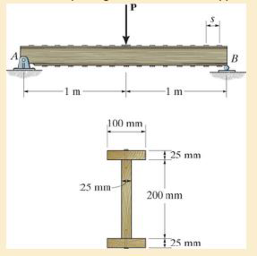
Probs. 7–40/41
Expert Solution & Answer
Want to see the full answer?
Check out a sample textbook solution
Students have asked these similar questions
The stepped bar has a thickness of 10 mm. Determine the maximum moment that can be applied to its ends if the allowable bending stress is sallow = 150 MPa.
20 mm
20 mm
4. The simply supported beam on the right
is built up from three boards by nailing
them together as shown. If P = 12 kN,
determine the maximum allowable spacing
s of the nails to support the load, if each
nail can resist a shear force of 1.5 kN.
1 m
m
B
100 mm
25 mm-
25 mm
200 mm
25 mm
The box beam is constructed from four boards that are fastened together using nails spaced along the beam every 2 in. If a force P = 2 kip is applied to the beam, determine the shear force resisted by each nail at A and B.
Chapter 7 Solutions
Mechanics of Materials
Ch. 7.2 - In each case, calculate the value of Q and t that...Ch. 7.2 - If the beam is subjected to a shear force of V =...Ch. 7.2 - Determine the shear stress at points A and B if...Ch. 7.2 - Determine the absolute maximum shear stress in the...Ch. 7.2 - If the beam is subjected to a shear force of V =20...Ch. 7.2 - If the beam is made from four plates and subjected...Ch. 7.2 - If the wide-flange beam is subjected to a shear of...Ch. 7.2 - If the wide-flange beam is subjected to a shear of...Ch. 7.2 - If the wide-flange beam is subjected to a shear of...Ch. 7.2 - Prob. 7.4P
Ch. 7.2 - Prob. 7.5PCh. 7.2 - The wood beam has an allowable shear stress of...Ch. 7.2 - The shaft is supported by a thrust bearing at A...Ch. 7.2 - The shaft is supported by a thrust bearing at A...Ch. 7.2 - Determine the largest shear force V that the...Ch. 7.2 - If the applied shear force V = 18 kip, determine...Ch. 7.2 - The overhang beam is subjected to the uniform...Ch. 7.2 - *7-12. The beam has a rectangular cross section...Ch. 7.2 - Determine the maximum shear stress in the strut if...Ch. 7.2 - Determine the maximum shear force V that the strut...Ch. 7.2 - 7-15. The strut is subjected to a vertical shear...Ch. 7.2 - Prob. 7.16PCh. 7.2 - If the beam is subjected to a shear of V=15 kN,...Ch. 7.2 - If the wide-flange beam is subjected to a shear of...Ch. 7.2 - If the wide-flange beam is subjected to a shear of...Ch. 7.2 - Prob. 7.20PCh. 7.2 - If the beam is made from wood having an allowable...Ch. 7.2 - Determine the shear stress at point B on the web...Ch. 7.2 - Determine the maximum shear stress acting at...Ch. 7.2 - Prob. 7.24PCh. 7.2 - 7-25. Determine the maximum shear stress in the...Ch. 7.2 - 7-26. The beam has a square cross section and is...Ch. 7.2 - The beam is slit longitudinally along both sides....Ch. 7.2 - The beam is to be cut longitudinally along both...Ch. 7.2 - The beam has a rectangular cross section and is...Ch. 7.2 - The beam in Fig.6-48f is subjected to a fully...Ch. 7.3 - The two identical boards are bolted together to...Ch. 7.3 - Two identical 20-mm-thick plates are bolted to the...Ch. 7.3 - The boards are bolted together to form the...Ch. 7.3 - The boards are bolted together to form the...Ch. 7.3 - Prob. 7.32PCh. 7.3 - Prob. 7.33PCh. 7.3 - Prob. 7.34PCh. 7.3 - Prob. 7.35PCh. 7.3 - Prob. 7.36PCh. 7.3 - Prob. 7.37PCh. 7.3 - Prob. 7.38PCh. 7.3 - A beam is constructed from three boards bolted...Ch. 7.3 - The simply supported beam is built up from three...Ch. 7.3 - The simply supported beam is built up from three...Ch. 7.3 - The T-beam is constructed as shown. If each nail...Ch. 7.3 - Prob. 7.43PCh. 7.3 - Prob. 7.44PCh. 7.3 - Prob. 7.45PCh. 7.3 - 7–46. The beam is subjected to a shear of V = 800...Ch. 7.3 - The beam is made from four boards nailed together...Ch. 7.3 - The beam is made from three polystyrene strips...Ch. 7.5 - A shear force of V=300 kN is applied to the box...Ch. 7.5 - A shear force of V=450 kN is applied to the box...Ch. 7.5 - A shear force of V = 18 kN is applied to the box...Ch. 7.5 - A shear force of V = 18 kN is applied to the box...Ch. 7.5 - The aluminum strut is 10 mm thick and has the...Ch. 7.5 - The aluminum strut is 10 mm thick and has the...Ch. 7.5 - Prob. 7.56PCh. 7.5 - Prob. 7.57PCh. 7.5 - Prob. 7.58PCh. 7.5 - Prob. 7.59PCh. 7.5 - The built-up beam is formed by welding together...Ch. 7.5 - The assembly is subjected to a vertical shear of V...Ch. 7.5 - 7–62. Determine the shear-stress variation over...Ch. 7.5 - 7–63. Determine the location e of the shear...Ch. 7.5 - Determine the location e of the shear center,...Ch. 7.5 - The beam supports a vertical shear of V=7 kip....Ch. 7.5 - The stiffened beam is constructed from plates...Ch. 7.5 - The pipe is subjected to a shear force of V=8 kip....Ch. 7.5 - *7–68. A thin plate of thickness t is bent to form...Ch. 7.5 - A thin plate of thickness t is bent to form the...Ch. 7.5 - 7–70. Determine the location e of the shear...Ch. 7 - The beam is fabricated from four boards nailed...Ch. 7 - The T-beam is subjected to a shear of V = 150 kN....Ch. 7 - The member is subject to a shear force of V = 2...Ch. 7 - Determine the shear stress at points B and C on...Ch. 7 - Determine the maximum shear stress acting at...
Knowledge Booster


Learn more about
Need a deep-dive on the concept behind this application? Look no further. Learn more about this topic, mechanical-engineering and related others by exploring similar questions and additional content below.Similar questions
- A wooden beam is fabricated by bolting together three members as shown. The 8-mm- diameter bolts are spaced at intervals of s= 200 mm along the x axis of the beam. If the internal shear force in the beam is V=7 kN, determine the shear stress in each bolt. 40 mm 40 mm 90 mm 40 mm 300 mmarrow_forwardThe beam is constructed from two boards fastened together at the top and bottom with three rows of nails spaced every 8 in. If an internal shear force of V = 800 lb is applied to the boards, determine the shear force resisted by each nail.arrow_forward5. If the radius of each notch on the pictured bending plate is r = 10 mm, determine the largest moment M that can be applied if the loading is of fatigue nature and the maximum allowable bending stress is 180 MPa. 20 mm 125 mm- 165 mm Marrow_forward
- The member has a circular cross section. If the allowable bending stress is sallow = 100 MPa, determine the maximum moment M that can be applied to the memberarrow_forwardDetermine the maximum shear stress acting in the fiberglass beam at the section where the internal shears force is maximum. (t1=15 mm, t2=20 mm, h=150 mm, b=50mm)arrow_forward10-26. A beam is made up of four 50 X 100-mm full-sized Douglas Fir pieces that are glued to a 25 x 500-mm Douglas Fir plywood web, as shown in the figure. Determine the maximum allowable shear and the maximum allowable bending moment that this section can carry if the allowable bending stress is 10 MPa; the allowable shear stress in plywood is 600 KN /m, and the allowable shearing stress in the glued joints is 300 kN/m^2. AIl dimensions in the figure are in mm.arrow_forward
- Determine the internal normal force, shear force, and bending moment at point C in the beam. 10 kN 60 kN-m A- B- - 2 m- m--1 m- -2 m-arrow_forwardThe bar has a thickness of 1 in. and the allowable bending stress is sallow= 30 ksi. Determine the maximum moment M that can be applied.arrow_forwardThe stepped bar has a thickness of 15 mm. Determine the maximum moment that can be applied to its ends if it is made of a material having an allowable bending stress of 200 MPa. 45 mm 30 mm 3 mm 10 mm 6 mm Marrow_forward
- The shaft is supported by a smooth thrust bearing at A and smooth journal bearing at C. If d = 3 in., determine the absolute maximum bending stress in the shaft.arrow_forwardDetermine the equations of bending moment and shear force for 0arrow_forwardDetermine the maximum bending stress in the handle of the cable cutter at section a–a. A force of 45 lb is applied to the handles.arrow_forwardarrow_back_iosSEE MORE QUESTIONSarrow_forward_ios
Recommended textbooks for you
 Elements Of ElectromagneticsMechanical EngineeringISBN:9780190698614Author:Sadiku, Matthew N. O.Publisher:Oxford University Press
 Mechanics of Materials (10th Edition)Mechanical EngineeringISBN:9780134319650Author:Russell C. HibbelerPublisher:PEARSON
 Thermodynamics: An Engineering ApproachMechanical EngineeringISBN:9781259822674Author:Yunus A. Cengel Dr., Michael A. BolesPublisher:McGraw-Hill Education
 Control Systems EngineeringMechanical EngineeringISBN:9781118170519Author:Norman S. NisePublisher:WILEY
 Mechanics of Materials (MindTap Course List)Mechanical EngineeringISBN:9781337093347Author:Barry J. Goodno, James M. GerePublisher:Cengage Learning
 Engineering Mechanics: StaticsMechanical EngineeringISBN:9781118807330Author:James L. Meriam, L. G. Kraige, J. N. BoltonPublisher:WILEY
Elements Of Electromagnetics
Mechanical Engineering
ISBN:9780190698614
Author:Sadiku, Matthew N. O.
Publisher:Oxford University Press
Mechanics of Materials (10th Edition)
Mechanical Engineering
ISBN:9780134319650
Author:Russell C. Hibbeler
Publisher:PEARSON
Thermodynamics: An Engineering Approach
Mechanical Engineering
ISBN:9781259822674
Author:Yunus A. Cengel Dr., Michael A. Boles
Publisher:McGraw-Hill Education
Control Systems Engineering
Mechanical Engineering
ISBN:9781118170519
Author:Norman S. Nise
Publisher:WILEY
Mechanics of Materials (MindTap Course List)
Mechanical Engineering
ISBN:9781337093347
Author:Barry J. Goodno, James M. Gere
Publisher:Cengage Learning
Engineering Mechanics: Statics
Mechanical Engineering
ISBN:9781118807330
Author:James L. Meriam, L. G. Kraige, J. N. Bolton
Publisher:WILEY
Mechanics of Materials Lecture: Beam Design; Author: UWMC Engineering;https://www.youtube.com/watch?v=-wVs5pvQPm4;License: Standard Youtube License