
Vector Mechanics for Engineers: Statics
12th Edition
ISBN: 9781259977268
Author: Ferdinand P. Beer, E. Russell Johnston Jr., David Mazurek
Publisher: McGraw-Hill Education
expand_more
expand_more
format_list_bulleted
Concept explainers
Videos
Textbook Question
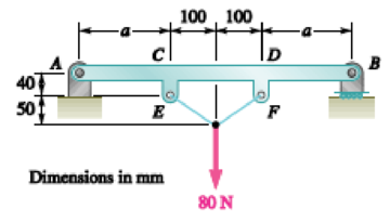
Chapter 7.2, Problem 7.57P
Determine (a) the distance a for which the maximum absolute value of the bending moment in beam AB is as small as possible, (b) the corresponding value of |M|max. (See the hint for Prob. 7.55.)
Expert Solution & Answer
Want to see the full answer?
Check out a sample textbook solution
Students have asked these similar questions
In order to reduce the bending moment in the cantilever beam AB , a cable and counterweight are permanently attached at end B . Determine the magnitude of the counterweight for which the maximum absolute value of the bending moment in the beam is as small as possible and the corresponding value of |M| max. Consider (a) the case when the distributed load is permanently applied to the beam, (b) the more general case when the distributed load may either be applied or removed.
5.14. A carriage spring centrally loaded and simply
supported at the ends has 10 steel plates each 5 cm wide by 6 mm thíck.
If the longest plate is 75 cm long, determine the initial radius of curva-
ture of the plates when the greatest bending stress is 800 MPa and the
plates are finally straight. Neglecting the loss of energy at impact, find
the greatest height from which a mass weighing 250 N may be dropped
centrally on the spring without exceeding the limiting bending stress of
800 MPa. Take E = 210 GPa.
%3D
Draw the shearing-force and bending-moment diagrams for the following beams:
1. A cantilever of length 20 m carrying a load of 10 kN at a distance of 15 m from the supported end.
2. A cantilever of length 20 m carrying a load of 10 kN is uniformly distributed over the inner 15 m of its length.
3. A cantilever of length 12 m carrying a load of 8 kN, applied 5 m from the supported end, and a load of 2kNlm over its whole length.
Chapter 7 Solutions
Vector Mechanics for Engineers: Statics
Ch. 7.1 - 7.1 and 7.2 Determine the internal forces (axial...Ch. 7.1 - Prob. 7.2PCh. 7.1 - Determine the internal forces at point J when =...Ch. 7.1 - Fig. P7.3 and P7.4 7.4 Determine the internal...Ch. 7.1 - Determine the internal forces at point J when =...Ch. 7.1 - Fig. P7.5 and P7.6 7.6 Determine the internal...Ch. 7.1 - An archer aiming at a target is pulling with a...Ch. 7.1 - For the bow of Prob. 7.7, determine the magnitude...Ch. 7.1 - A semicircular rod is loaded as shown. Determine...Ch. 7.1 - A semicircular rod is loaded as shown. Determine...
Ch. 7.1 - A semicircular rod is loaded as shown. Determine...Ch. 7.1 - Fig. P7.11 and P7.12 7.12 A semicircular rod is...Ch. 7.1 - The axis of the curved member AB is a parabola...Ch. 7.1 - Knowing that the axis of the curved member AB is a...Ch. 7.1 - Knowing that the radius of each pulley is 120 mm...Ch. 7.1 - Fig. P7.15 and P7.16 7.16 Knowing that the radius...Ch. 7.1 - A 5-in.-diameter pipe is supported every 9 ft by a...Ch. 7.1 - For the frame of Prob. 7.17, determine the...Ch. 7.1 - Knowing that the radius of each pulley is 200 mm...Ch. 7.1 - Fig. P7.19 and P7.20 7.20 Knowing that the radius...Ch. 7.1 - and 7.22 A force P is applied to a bent rod that...Ch. 7.1 - and 7.22 A force P is applied to a bent rod that...Ch. 7.1 - A quarter-circular rod of weight W and uniform...Ch. 7.1 - For the rod of Prob. 7.23, determine the magnitude...Ch. 7.1 - A semicircular rod of weight W and uniform cross...Ch. 7.1 - A semicircular rod of weight W and uniform cross...Ch. 7.1 - 7.27 and 7.28 A half section of pipe rests on a...Ch. 7.1 - 7.27 and 7.28 A half section of pipe rests on a...Ch. 7.2 - 7.29 through 7.32 For the beam and loading shown,...Ch. 7.2 - 7.29 through 7.32 For the beam and loading shown,...Ch. 7.2 - 7.29 through 7.32 For the beam and loading shown,...Ch. 7.2 - 7.29 through 7.32 For the beam and loading shown,...Ch. 7.2 - 7.33 and 7.34 For the beam and loading shown, (a)...Ch. 7.2 - 7.33 and 7.34 For the beam and loading shown, (a)...Ch. 7.2 - 7.35 and 7.36 For the beam and loading shown, (a)...Ch. 7.2 - 7.35 and 7.36 For the beam and loading shown, (a)...Ch. 7.2 - 7.37 and 7.38 For the beam and loading shown, (a)...Ch. 7.2 - 7.37 and 7.38 For the beam and loading shown, (a)...Ch. 7.2 - For the beam and loading shown, (a) draw the shear...Ch. 7.2 - For the beam and loading shown, (a) draw the shear...Ch. 7.2 - For the beam and loading shown, (a) draw the shear...Ch. 7.2 - For the beam and loading shown, (a) draw the shear...Ch. 7.2 - Assuming the upward reaction of the ground on beam...Ch. 7.2 - Solve Problem 7.43 knowing that P = 3wa. PROBLEM...Ch. 7.2 - Assuming the upward reaction of the ground on beam...Ch. 7.2 - Solve Prob. 7.45 assuming that the 12-kip load has...Ch. 7.2 - Assuming the upward reaction of the ground on beam...Ch. 7.2 - Prob. 7.48PCh. 7.2 - Draw the shear and bending-moment diagrams for the...Ch. 7.2 - Draw the shear and bending-moment diagrams for the...Ch. 7.2 - Draw the shear and bending-moment diagrams for the...Ch. 7.2 - Draw the shear and bending-moment diagrams for the...Ch. 7.2 - Two small channel sections DF and EH have been...Ch. 7.2 - Solve Prob. 7.53 when = 60. PROBLEM 7.53 Two...Ch. 7.2 - For the structural member of Prob. 7.53, determine...Ch. 7.2 - For the beam of Prob. 7.43, determine (a) the...Ch. 7.2 - Determine (a) the distance a for which the maximum...Ch. 7.2 - For the beam and loading shown, determine (a) the...Ch. 7.2 - A uniform beam is to be picked up by crane cables...Ch. 7.2 - Knowing that P = Q = 150 lb, determine (a) the...Ch. 7.2 - Knowing that P = Q = 150 lb, determine (a) the...Ch. 7.2 - In order to reduce the bending moment in the...Ch. 7.3 - Using the method of Sec. 7.3, solve Prob. 7.29....Ch. 7.3 - Prob. 7.64PCh. 7.3 - Using the method of Sec. 7.3, solve Prob. 7.31....Ch. 7.3 - Prob. 7.66PCh. 7.3 - Using the method of Sec. 7.3, solve Prob. 7.33....Ch. 7.3 - Using the method of Sec. 7.3, solve Prob. 7.34....Ch. 7.3 - 7.69 and 7.70 For the beam and loading shown, (a)...Ch. 7.3 - 7.69 and 7.70 For the beam and loading shown, (a)...Ch. 7.3 - Using the method of Sec. 7.3, solve Prob. 7.39....Ch. 7.3 - Using the method of Sec. 7.3, solve Prob. 7.40....Ch. 7.3 - Using the method of Sec. 7.3, solve Prob. 7.41....Ch. 7.3 - Using the method of Sec. 7.3, solve Prob. 7.42....Ch. 7.3 - 7.75 and 7.76 For the beam and loading shown, (a)...Ch. 7.3 - Prob. 7.76PCh. 7.3 - For the beam and loading shown, (a) draw the shear...Ch. 7.3 - For the beam and loading shown, (a) draw the shear...Ch. 7.3 - For the beam and loading shown, (a) draw the shear...Ch. 7.3 - For the beam and loading shown, (a) draw the shear...Ch. 7.3 - For the beam and loading shown, (a) draw the shear...Ch. 7.3 - For the beam and loading shown, (a) draw the shear...Ch. 7.3 - (a) Draw the shear and bending-moment diagrams for...Ch. 7.3 - Solve Prob. 7.83 assuming that the 300-lb force...Ch. 7.3 - For the beam and loading shown, (a) write the...Ch. 7.3 - For the beam and loading shown, (a) write the...Ch. 7.3 - For the beam and loading shown, (a) write the...Ch. 7.3 - For the beam and loading shown, (a) write the...Ch. 7.3 - The beam AB supports the uniformly distributed...Ch. 7.3 - Solve Prob. 7.89 assuming that the uniformly...Ch. 7.3 - The beam AB is subjected to the uniformly...Ch. 7.3 - Prob. 7.92PCh. 7.4 - Three loads are suspended as shown from the cable...Ch. 7.4 - Knowing that the maximum tension in cable ABCDE is...Ch. 7.4 - If dA = 8 ft and dc = 10 ft, determine the...Ch. 7.4 - Prob. 7.96PCh. 7.4 - Knowing that dc = 5 m, determine (a) the distances...Ch. 7.4 - Prob. 7.98PCh. 7.4 - Knowing that dc = 9 ft, determine (a) the...Ch. 7.4 - Prob. 7.100PCh. 7.4 - Knowing that mB = 70 kg and mC = 25 kg, determine...Ch. 7.4 - Fig. P7.101 and P7.102 7.102 Knowing that mB = 18...Ch. 7.4 - Cable ABC supports two loads as shown. Knowing...Ch. 7.4 - Prob. 7.104PCh. 7.4 - If a = 3 m, determine the magnitudes of P and Q...Ch. 7.4 - If a = 4 m, determine the magnitudes of P and Q...Ch. 7.4 - An electric wire having a mass per unit length of...Ch. 7.4 - The total mass of cable ACB is 20 kg. Assuming...Ch. 7.4 - The center span of the George Washington Bridge,...Ch. 7.4 - The center span of the Verrazano-Narrows Bridge...Ch. 7.4 - Each cable of the Golden Gate Bridge supports a...Ch. 7.4 - Two cables of the same gauge are attached to a...Ch. 7.4 - A 76-m length of wire having a mass per unit...Ch. 7.4 - A cable of length L + is suspended between two...Ch. 7.4 - The total mass of cable AC is 25 kg. Assuming that...Ch. 7.4 - Cable ACB supports a load uniformly distributed...Ch. 7.4 - Each cable of the side spans of the Golden Gate...Ch. 7.4 - A steam pipe weighing 45 lb/ft that passes between...Ch. 7.4 - A cable AB of span L and a simple beam AB of the...Ch. 7.4 - Making use of the property established in Prob....Ch. 7.4 - 7.120 through 7.123 Making use of the property...Ch. 7.4 - 7.120 through 7.123 Making use of the property...Ch. 7.4 - Prob. 7.123PCh. 7.4 - Prob. 7.124PCh. 7.4 - Using the property indicated in Prob. 7.124,...Ch. 7.4 - If the weight per unit length of the cable AB is...Ch. 7.5 - A 25-ft chain with a weight of 30 lb is suspended...Ch. 7.5 - A 500-ft-long aerial tramway cable having a weight...Ch. 7.5 - A 40-m cable is strung as shown between two...Ch. 7.5 - A 50-m steel surveying tape has a mass of 1.6 kg....Ch. 7.5 - Prob. 7.131PCh. 7.5 - Prob. 7.132PCh. 7.5 - A 20-m length of wire having a mass per unit...Ch. 7.5 - Determine the sag of a 30-ft chain that is...Ch. 7.5 - Prob. 7.135PCh. 7.5 - Prob. 7.136PCh. 7.5 - A cable weighing 2 lb/ft is suspended between two...Ch. 7.5 - Prob. 7.138PCh. 7.5 - Prob. 7.139PCh. 7.5 - Fig. P7.139 and P7.140 7.140 A motor M is used to...Ch. 7.5 - Prob. 7.141PCh. 7.5 - Prob. 7.142PCh. 7.5 - Prob. 7.143PCh. 7.5 - Prob. 7.144PCh. 7.5 - To the left of point B, the long cable ABDE rests...Ch. 7.5 - Fig. P7.145 and P7.146 7.146 To the left of point...Ch. 7.5 - The 10-ft cable AB is attached to two collars as...Ch. 7.5 - Prob. 7.148PCh. 7.5 - Prob. 7.149PCh. 7.5 - (a) Determine the maximum allowable horizontal...Ch. 7.5 - A cable has a mass per unit length of 3 kg/m and...Ch. 7.5 - Determine the sag-to-span ratio for which the...Ch. 7.5 - Prob. 7.153PCh. 7 - Knowing that the turnbuckle has been tightened...Ch. 7 - Knowing that the turnbuckle has been tightened...Ch. 7 - Two members, each consisting of a straight and a...Ch. 7 - Knowing that the radius of each pulley is 150 mm,...Ch. 7 - For the beam shown, determine (a) the magnitude P...Ch. 7 - For the beam and loading shown, (a) draw the shear...Ch. 7 - For the beam and loading shown, (a) draw the shear...Ch. 7 - For the beam shown, draw the shear and...Ch. 7 - The beam AB, which lies on the ground, supports...Ch. 7 - Two loads are suspended as shown from the cable...Ch. 7 - A wire having a mass per unit length of 0.65 kg/m...Ch. 7 - A 10-ft rope is attached to two supports A and B...
Knowledge Booster


Learn more about
Need a deep-dive on the concept behind this application? Look no further. Learn more about this topic, mechanical-engineering and related others by exploring similar questions and additional content below.Similar questions
- 9. Draw the shearing-force and bending-moment diagrams for the following beams: A cantilever of length 20 m carrying a load of 10 kN at a distance of 15 m from the supported end. A cantilever of length 20 m carrying a load of 10 KN uniformly distributed over the inner 15 m of its length. A cantilever of length 12 m carrying a load of 8 kN, applied 5 m from the supported end, and a load of 2kN/m over its whole length. A beam, 20 m span, simply-supported at each end and carrying a vertical load of 20 kN at a distance 5 m from one support. A beam, 16 m span, simply-supported at each end and carrying a vertical load of 2.5 kN at a distance of 4 m from one support and the beam itself weighing 500 N per i. ii. iii. iv. V. metre.arrow_forwardDetermine the bending moment acting at each of the following locations:(a) x = 13.5- ft (i.e., just to the left of point B)(b) x = 13.5+ ft(i.e., just to the right of point B)(c) x = 17.0 ft (i.e. at point C)(d) x = 23.0 ftNote that x = 0 at support A. When entering your answers, use the shear-force sign convention detailed in Section 7.2.Answers: (a) M = kips-ft (b) M = kips-ft (c) M = kips-ft (d) M = kips-ft Use your shear-force and bending-moment diagrams to determine the maximum positive bending moment, Mmax, pos, the maximum negative bending moment, Mmax, neg, and their respective locations, xmax, pos and xmax, neg. When entering your answers for the maximum bending moments, use the shear-force and bending-moment sign conventions detailed in Section 7.2. The maximum negative bending moment is the negative moment with the largest absolute value. Enter the maximum negative bending moment as a negative value.Answers: Mmax, pos = kips-ft xmax, pos = ft Mmax,…arrow_forward5.16 The box beam is made by nailing four 2-in. by 8-in. planks together as shown. (a) Show that the moment of inertia of the cross-sectional area about the neutral axis is 981.3 in.. (b) Given that wo 300 lb/ft, find the largest allowable force P if the bending stress is limited to 1400 psi. 8 in.2 in. 8 in. 9 f 3 ft 2 in. FIG. P5.16arrow_forward
- (a) A simply supported beam of length 6 m carries point loads of 5 kN each at a distance of 1.5 m and 3.5 m from the left end support. The beam carries a uniformly distributed load of 1 kN/m between the point loads. Draw the shear force and bending moment diagram.arrow_forwardAssuming the upward reaction of the ground on beam AB to be uniformly distributed, (a) draw the shear and bending-moment diagrams, (b) determine the maximum absolute values of the shear and bending moment.arrow_forwardThe figure shows a cantilever beam carrying a uniformly distributed load of 4 kN/m and a point load of 16 kN at distance 2 m from the free end. The shear force and bending moment at a position just to the right of point B is, 16 kN 4 kN/m A B 2 m 3 m O a. (-)8 kN, (-8) kNm O b.(-)24 kN, (-)8 kNm O. (-)24 kN, (-)16 kNm O d. Not determinable, (-)16 kNmarrow_forward
- Q2 :The railway wheel exerts a force on the rail and through the wooden beam, and the gravel can be assumed as a reaction over the length of the wooden beam, as shown in Fig. Q2. (a) Draw the shear force and bending moment diagrams for the beam and determine the magnitude of the maximum load w per kN/m. (b) If the allowable bending stress is 10 MN/m² and the aspect ratio of the rectangular wood beam is h/b = 0.5, determine the minimum width b and height h that can be used for the beam. 60 kN Į 45 cm 60 KN Uniform Reaction w kN/m 150 cm 45 cm Fig. Q2 Railway Loadingarrow_forwardTwo live loads of 7 KN and 9 KN separated 5 m apart, are to cross a simple beam. Also, a uniform live load of 6 KN/m, 6 m long, is expected to cross the same beam. The simple supports are marked A and B and a point C is located 4 m from A. Determine: (a) the maximum moment at C due to the two concentrated live loads if the length of the beam is (a.1) 8.4 m; (a.2) 10 m. (b) The maximum moment at C due to the uniform live load if the length of the beam is (b.1) 8.4 m; (b.2) 10 m. (c) The maximum moment in the beam due to the combined effects of the two concentrated live loads and the uniform live loads if the length of the beam is (c.1) 8.4 m; (c.2) 10 m. part (c), I am asking for the ABSOLUTE maximum moment in the beam due to the combined effects of the two live loads and the uniform live load. Please be guided and informed accordingly. Good luck!arrow_forwardA cable AB of span L and a simple beam A'B' of the same span are subjected to identical vertical loadings as shown. Show that the magnitude of the bending moment at a point C' in the beam is equal to the product T0h, where T0 is the magnitude of the horizontal component of the tension force in the cable and h is the vertical distance between point C and the chord joining the points of support A and B.arrow_forward
- 0.6 m 25 kN/m 40 kN 1.8 m 40 KN C 0.6 m D PROBLEM 5.108 (a) Using singularity functions, write the equations for the shear and bending moment for the beam and loading shown. (b) Determine the maximum value of the bending moment in the beam.arrow_forwardProb. #2. An overhanging beam with a length of 12 ft. is fixed at the left end. It has a load of uniformly distributed load of 100 lb/ft located 4 ft fr. The left support and covers the remaining length of the beam. Draw completely the shear and bending moment for this beam.arrow_forwardThe figure shows a cantilever beam carrying a uniformly distributed load of 4 kN/m and a point load of 16 kN at distance 2 m from the free end. The shear force and bending moment at a position just to the right of point B is, 16 kN 4 kN/m C 2 m 3 m O a. (-)8 kN, (-8) kNm O b.(-)24 kN, (-)16 kNm Oc. Not determinable, (-)16 kNm Od. (-)24 kN, (-)8 kNmarrow_forward
arrow_back_ios
SEE MORE QUESTIONS
arrow_forward_ios
Recommended textbooks for you
 Elements Of ElectromagneticsMechanical EngineeringISBN:9780190698614Author:Sadiku, Matthew N. O.Publisher:Oxford University Press
 Mechanics of Materials (10th Edition)Mechanical EngineeringISBN:9780134319650Author:Russell C. HibbelerPublisher:PEARSON
 Thermodynamics: An Engineering ApproachMechanical EngineeringISBN:9781259822674Author:Yunus A. Cengel Dr., Michael A. BolesPublisher:McGraw-Hill Education
 Control Systems EngineeringMechanical EngineeringISBN:9781118170519Author:Norman S. NisePublisher:WILEY
 Mechanics of Materials (MindTap Course List)Mechanical EngineeringISBN:9781337093347Author:Barry J. Goodno, James M. GerePublisher:Cengage Learning
 Engineering Mechanics: StaticsMechanical EngineeringISBN:9781118807330Author:James L. Meriam, L. G. Kraige, J. N. BoltonPublisher:WILEY
Elements Of Electromagnetics
Mechanical Engineering
ISBN:9780190698614
Author:Sadiku, Matthew N. O.
Publisher:Oxford University Press
Mechanics of Materials (10th Edition)
Mechanical Engineering
ISBN:9780134319650
Author:Russell C. Hibbeler
Publisher:PEARSON
Thermodynamics: An Engineering Approach
Mechanical Engineering
ISBN:9781259822674
Author:Yunus A. Cengel Dr., Michael A. Boles
Publisher:McGraw-Hill Education
Control Systems Engineering
Mechanical Engineering
ISBN:9781118170519
Author:Norman S. Nise
Publisher:WILEY
Mechanics of Materials (MindTap Course List)
Mechanical Engineering
ISBN:9781337093347
Author:Barry J. Goodno, James M. Gere
Publisher:Cengage Learning
Engineering Mechanics: Statics
Mechanical Engineering
ISBN:9781118807330
Author:James L. Meriam, L. G. Kraige, J. N. Bolton
Publisher:WILEY
Everything About COMBINED LOADING in 10 Minutes! Mechanics of Materials; Author: Less Boring Lectures;https://www.youtube.com/watch?v=N-PlI900hSg;License: Standard youtube license