
Vector Mechanics for Engineers: Statics
12th Edition
ISBN: 9781259977268
Author: Ferdinand P. Beer, E. Russell Johnston Jr., David Mazurek
Publisher: McGraw-Hill Education
expand_more
expand_more
format_list_bulleted
Videos
Textbook Question
Chapter 6.4, Problem 6.131P
Arm ABC is connected by pins to a collar at B and to crank CD at C. Neglecting the effect of friction, determine the couple M required to hold the system in equilibrium when θ = 0.
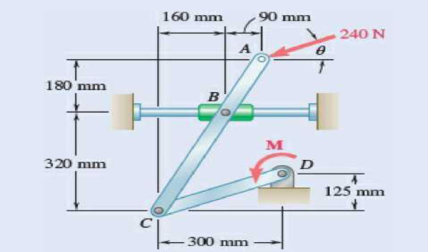
Fig. P6.131 and P6.132
Expert Solution & Answer
Want to see the full answer?
Check out a sample textbook solution
Students have asked these similar questions
A 200-kg crate is to be supported by the rope-and-pulley arrangement shown. Determine the magnitude and direction of the force P that must be exerted on the free end of the rope to maintain equilibrium. (Hint: The tension in the rope is the same on each side of a simple pulley. This can be proved by the methods of Chap. 4.)
A couple M with a magnitude of 100 N.m is applied as shown to the crank of the engine system. Knowing that AB = 50 mm and BC = 200 mm, determine the force P required to maintain the equilibrium of the system when (a) θ= 60°, (b) θ= 120°.
Q.4. Determine the force F required to hold the system in equilibrium if a torque M of 240 N-m
is applied at point D in the counter-clockwise direction. Assume the weights of all members are
negligible and that collar B freely moves along the horizontal rod with negligible friction.
160 mm 90 mm
180 mm
B
M
320 mm
D
125 mm
300 mm
Chapter 6 Solutions
Vector Mechanics for Engineers: Statics
Ch. 6.1 - Using the method of joints, determine the force in...Ch. 6.1 - Using the method of joints, determine the force in...Ch. 6.1 - Using the method of joints, determine the force in...Ch. 6.1 - Using the method of joints, determine the force in...Ch. 6.1 - Using the method of joints, determine the force in...Ch. 6.1 - Using the method of joints, determine the force in...Ch. 6.1 - Using the method of joints, determine the force in...Ch. 6.1 - Using the method of joints, determine the force in...Ch. 6.1 - Using the method of joints, determine the force in...Ch. 6.1 - Determine the force in each member of the truss...
Ch. 6.1 - Determine the force in each member of the Gambrel...Ch. 6.1 - Determine the force in each member of the Howe...Ch. 6.1 - Using the method of joints, determine the force in...Ch. 6.1 - Prob. 6.14PCh. 6.1 - Determine the force in each member of the Warren...Ch. 6.1 - Solve Problem 6.15 assuming that the load applied...Ch. 6.1 - Determine the force in each member of the Pratt...Ch. 6.1 - The truss shown is one of several supporting an...Ch. 6.1 - Determine the force in each member of the Pratt...Ch. 6.1 - Solve Problem 6.19 assuming that the load applied...Ch. 6.1 - Determine the force in each of the members located...Ch. 6.1 - Determine the force in member DE and in each of...Ch. 6.1 - Determine the force in each of the members located...Ch. 6.1 - The portion of truss shown represents the upper...Ch. 6.1 - For the tower and loading of Prob. 6.24 and...Ch. 6.1 - Solve Problem 6.24 assuming that the cables...Ch. 6.1 - Determine the force in each member of the truss...Ch. 6.1 - Determine the force in each member of the truss...Ch. 6.1 - Determine whether the trusses of Problems 6.31a,...Ch. 6.1 - Determine whether the trusses of Problems 6.31b,...Ch. 6.1 - For the given loading, determine the zero-force...Ch. 6.1 - For the given loading, determine the zero-force...Ch. 6.1 - For the given loading, determine the zero-force...Ch. 6.1 - Determine the zero-force members in the truss of...Ch. 6.1 - The truss shown consists of six members and is...Ch. 6.1 - The truss shown consists of six members and is...Ch. 6.1 - The truss shown consists of six members and is...Ch. 6.1 - Prob. 6.38PCh. 6.1 - The truss shown consists of nine members and is...Ch. 6.1 - Solve Prob. 6.39 for P = 0 and Q = (900 N)k. 6.39...Ch. 6.1 - The truss shown consists of 18 members and is...Ch. 6.1 - The truss shown consists of 18 members and is...Ch. 6.2 - Determine the force in members BD and DE of the...Ch. 6.2 - Determine the force in members DG and EG of the...Ch. 6.2 - Determine the force in members BD and CD of the...Ch. 6.2 - Determine the force in members DF and DG of the...Ch. 6.2 - A floor truss is loaded as shown. Determine the...Ch. 6.2 - A floor truss is loaded as shown. Determine the...Ch. 6.2 - Determine the force in members CD and DF of the...Ch. 6.2 - Determine the force in members CE and EF of the...Ch. 6.2 - Determine the force in members DE and DF of the...Ch. 6.2 - Determine the force in members EG and EF of the...Ch. 6.2 - Determine the force in members DF and DE of the...Ch. 6.2 - Determine the force in members CD and CE of the...Ch. 6.2 - A Pratt roof truss is loaded as shown. Determine...Ch. 6.2 - A Pratt roof truss is loaded as shown. Determine...Ch. 6.2 - A Howe scissors roof truss is loaded as shown....Ch. 6.2 - A Howe scissors roof truss is loaded as shown....Ch. 6.2 - Determine the force in members AD, CD, and CE of...Ch. 6.2 - Determine the force in members DG, FG, and FH of...Ch. 6.2 - Determine the force in member GJ of the truss...Ch. 6.2 - Determine the force in members DG and FH of the...Ch. 6.2 - Prob. 6.63PCh. 6.2 - Prob. 6.64PCh. 6.2 - The diagonal members in the center panels of the...Ch. 6.2 - The diagonal members in the center panels of the...Ch. 6.2 - The diagonal members in the center panels of the...Ch. 6.2 - Solve Prob. 6.67 assuming that the 9-kip load has...Ch. 6.2 - Classify each of the structures shown as...Ch. 6.2 - Classify each of the structures shown as...Ch. 6.2 - 6.70 through 6.74 classify as determinate or...Ch. 6.2 - 6.70 through 6.74 classify as determinate or...Ch. 6.2 - 6.70 through 6.74 classify as determinate or...Ch. 6.2 - 6.70 through 6.74 classify as determinate or...Ch. 6.3 - For the frame and loading shown, draw the...Ch. 6.3 - For the frame and loading shown, draw the...Ch. 6.3 - Draw the free-body diagram(s) needed to determine...Ch. 6.3 - Knowing that the pulley has a radius of 0.5 m,...Ch. 6.3 - and 6.76 Determine the force in member BD and the...Ch. 6.3 - Prob. 6.76PCh. 6.3 - For the frame and loading shown, determine the...Ch. 6.3 - Determine the components of all forces acting on...Ch. 6.3 - The hydraulic cylinder CF, which partially...Ch. 6.3 - The hydraulic cylinder CF, which partially...Ch. 6.3 - Determine the components of all forces acting on...Ch. 6.3 - Determine the components of all forces acting on...Ch. 6.3 - Determine the components of the reactions at A and...Ch. 6.3 - Determine the components of the reactions at D and...Ch. 6.3 - Determine the components of the reactions at A and...Ch. 6.3 - Determine the components of the reactions at A and...Ch. 6.3 - Determine the components of the reactions at A and...Ch. 6.3 - The 48-lb load can be moved along the line of...Ch. 6.3 - The 48-lb load is removed and a 288-lb in....Ch. 6.3 - (a) Show that, when a frame supports a pulley at...Ch. 6.3 - Knowing that each pulley has a radius of 250 mm,...Ch. 6.3 - Knowing that the pulley has a radius of 75 mm,...Ch. 6.3 - Prob. 6.93PCh. 6.3 - Prob. 6.94PCh. 6.3 - A trailer weighing 2400 lb is attached to a...Ch. 6.3 - In order to obtain a better weight distribution...Ch. 6.3 - The cab and motor units of the front-end loader...Ch. 6.3 - Solve Problem 6.97 assuming that the 75-kN load...Ch. 6.3 - Knowing that P = 90 lb and Q = 60 lb, determine...Ch. 6.3 - Knowing that P = 90 lb and Q = 60 lb, determine...Ch. 6.3 - For the frame and loading shown, determine the...Ch. 6.3 - For the frame and loading shown, determine the...Ch. 6.3 - Prob. 6.103PCh. 6.3 - Prob. 6.104PCh. 6.3 - For the frame and loading shown, determine the...Ch. 6.3 - Solve Prob. 6.105 assuming that the 6-kN load has...Ch. 6.3 - The axis of the three-hinge arch ABC is a parabola...Ch. 6.3 - The axis of the three-hinge arch ABC is a parabola...Ch. 6.3 - 6.109 and 6.110 Neglecting the effect of friction...Ch. 6.3 - and 6.110 Neglecting the effect of friction at the...Ch. 6.3 - 6.111, 6.112, and 6.113 Members ABC and CDE are...Ch. 6.3 - 6.111, 6.112, and 6.113 Members ABC and CDE are...Ch. 6.3 - 6.111, 6.112, and 6.113 Members ABC and CDE are...Ch. 6.3 - Members ABC and CDE are pin-connected at C and...Ch. 6.3 - Solve Prob. 6.112 assuming that the force P is...Ch. 6.3 - Solve Prob. 6.114 assuming that the force P is...Ch. 6.3 - Four beams, each with a length of 2a, are nailed...Ch. 6.3 - Four beams, each with a length of 3a, are held...Ch. 6.3 - 6.119 through 6.121 Each of the frames shown...Ch. 6.3 - 6.119 through 6.121 Each of the frames shown...Ch. 6.3 - 6.119 through 6.121 Each of the frames shown...Ch. 6.4 - An 84-lb force is applied to the toggle vise at C....Ch. 6.4 - For the system and loading shown, draw the...Ch. 6.4 - A small barrel weighing 60 lb is lifted by a pair...Ch. 6.4 - The position of member ABC is controlled by the...Ch. 6.4 - The shear shown is used to cut and trim...Ch. 6.4 - A 100-lb force directed vertically downward is...Ch. 6.4 - Prob. 6.124PCh. 6.4 - The control rod CE passes through a horizontal...Ch. 6.4 - Solve Prob. 6.125 when (a) = 0, (b) = 6. Fig....Ch. 6.4 - The press shown is used to emboss a small seal at...Ch. 6.4 - The press shown is used to emboss a small seal at...Ch. 6.4 - The pin at B is attached to member ABC and can...Ch. 6.4 - The pin at B is attached to member ABC and can...Ch. 6.4 - Arm ABC is connected by pins to a collar at B and...Ch. 6.4 - Arm ABC is connected by pins to a collar at B and...Ch. 6.4 - The Whitworth mechanism shown is used to produce a...Ch. 6.4 - Solve Prob. 6.133 when (a) = 60, (b) = 90. Fig....Ch. 6.4 - and 6.136 Two rods are connected by a slider block...Ch. 6.4 - and 6.136 Two rods are connected by a slider block...Ch. 6.4 - 6.137 and 6.138 Rod CD is attached to the collar D...Ch. 6.4 - 6.137 and 6.138 Rod CD is attached to the collar D...Ch. 6.4 - Two hydraulic cylinders control the position of...Ch. 6.4 - Two hydraulic cylinders control the position of...Ch. 6.4 - A steel ingot weighing 8000 lb is lifted by a pair...Ch. 6.4 - If the toggle shown is added to the tongs of Prob....Ch. 6.4 - A 9-m length of railroad rail of mass 40 kg/m is...Ch. 6.4 - The gear-pulling assembly shown consists of a...Ch. 6.4 - The pliers shown are used to grip a...Ch. 6.4 - Prob. 6.146PCh. 6.4 - In using the bolt cutter shown, a worker applies...Ch. 6.4 - The upper blade and lower handle of the...Ch. 6.4 - and 6.150 Determine the force P that must be...Ch. 6.4 - and 6.150 Determine the force P that must be...Ch. 6.4 - Because the brace shown must remain in position...Ch. 6.4 - The specialized plumbing wrench shown is used in...Ch. 6.4 - Prob. 6.153PCh. 6.4 - For the frame and loading shown, determine the...Ch. 6.4 - The telescoping arm ABC is used to provide an...Ch. 6.4 - The telescoping arm ABC of Prob. 6.155 can be...Ch. 6.4 - The motion of the backhoe bucket shown is...Ch. 6.4 - Solve Prob. 6.157 assuming that the 2-kip force P...Ch. 6.4 - The gears A and D are rigidly attached to...Ch. 6.4 - In the planetary gear system shown, the radius of...Ch. 6.4 - Two shafts AC and CF, which lie in the vertical xy...Ch. 6.4 - Two shafts AC and CF, which lie in the vertical xy...Ch. 6.4 - The large mechanical tongs shown are used to grab...Ch. 6 - Using the method of joints, determine the force in...Ch. 6 - Using the method of joints, determine the force in...Ch. 6 - A stadium roof truss is loaded as shown. Determine...Ch. 6 - A stadium roof truss is loaded as shown. Determine...Ch. 6 - Determine the components of all forces acting on...Ch. 6 - Determine the components of the reactions at A and...Ch. 6 - Knowing that the pulley has a radius of 50 mm,...Ch. 6 - For the frame and loading shown, determine the...Ch. 6 - For the frame and loading shown, determine the...Ch. 6 - Water pressure in the supply system exerts a...Ch. 6 - A couple M with a magnitude of 1.5 kNm is applied...Ch. 6 - The compound-lever pruning shears shown can be...
Knowledge Booster


Learn more about
Need a deep-dive on the concept behind this application? Look no further. Learn more about this topic, mechanical-engineering and related others by exploring similar questions and additional content below.Similar questions
- A 4-kN force P is applied as shown to the piston of the engine system. Knowing that AB = 50 mm and BC = 200 mm, determine the couple M required to maintain the equilibrium of the system when (a) θ= 30°, (b) θ= 150°.arrow_forwardTwo rods are connected by a slider block as shown. Given: MB= 250 lb-in. MA MB 25° 15 in. A |B 15 in.- Draw the free-body diagram needed to determine the couple MA required to hold the system in equilibrium.arrow_forward7.34 The cylinder and the block are connected by a horizontal cord. Determine the largest couple C that can be applied to the cylinder without disturbing the equilibrium of the system. Assume that both bodies are homogeneous.arrow_forward
- The lid of a roof scuttle weighs 75 lb. It is hinged at corners A and B and maintained in the desired position by a rod CD pivoted at C; a pin at end D of the rod fits into one of several holes drilled in the edge of the lid. For α=50°, determine (a) the magnitude of the force exerted by rod CD, (b) the reactions at the hinges. Assume that the hinge at B does not exert any axial thrust.arrow_forwardThree rods are welded together to form a "corner" that is supported by three eyebolts. Neglecting friction, determine the reactions at A, B, and C when P= 240 lb, a = 12 in., b= 8 in., and c= 10 in. Solve Prob. 4.127, assuming that the force P is removed and is replaced by a couple M = +(600 lb-in.)j acting at В. y Fig. P4.127arrow_forwardQuestion 4: (a) (i) State the Principle of Moment (Varignon's Theorem). (ii) Prove that the moment of a couple is the same about any axis perpendicular to the plane of action of the couple. (b) A uniform rod Whose centre of gravity G divides it into the ratio AG : GB = a :b is in limiting equilibrium at an angle a with the horizontal with its upper end B resting against a smooth peg and its lower end A attached to a light cord, which is fastened to a point C on the same level as B. Prove that the angle B at which the cord is inclined to the horizontal is given by the equation a+b b tanß = tana cot a a a Question 5: (a) From Lesotho Bank tower an object was observed on the ground at a depression o below the horizon. A gun was fired at an elevation a, but the shot missing the object, stuck the ground at a point whose depression was y. Prove that the correct elevation 0 of the gun is given by sin(20 +0) + sin(o) sin(2a+0) + sin(o) sin y (1+ cos(20)) sin o (1+cos(2y))arrow_forward
- At the lower left end A of the bar, bent into an isosceles right triangle, a vertical force F is applied. Knowing that the bar can rotate around point O determines the minimum magnitude of the force Q that must be applied at the other end B, so that it is in equilibrium:arrow_forwardA 5 x 8-ft sign of uniform density weighs 270 lb and is supported by a ball-and-socket joint at A and by two cables. Determine the tension in each cable and the reaction at A.arrow_forwardA freight wagon is at rest on a track at an angle of 25o to the vertical. The gross weight of the wagon and its load is 36kN and acts at a point 750 mm from the track, in the middle between the two axles. The wagon is held by a cable 600 mm from the track. Determine the traction on the cable and the reaction on each pair of wheels.arrow_forward
- Two rods are connected by a frictionless collar B. Knowing that the magnitude of the couple MA is 500 lb·in., determine (a) the couple MC required for equilibrium, (b) the corresponding components of the reaction at C.arrow_forwardA homogeneous hemisphere with a radius r is placed on an incline as shown. Assuming that friction is sufficient to prevent slipping between the hemisphere and the incline, determine (a) the largest angle β for which a position of equilibrium exists, (b) the angle 0 corresponding to equilibrium when the angle β is equal to half the value found in part a.arrow_forwardA 600-lb crate is supported by several rope-and-pulley arrangements as shown. Determine for each arrangement the tension in the rope. (Hint: The tension in the rope is the same on each side of a simple pulley. This can be proved by the methods of Chap. 4.)arrow_forward
arrow_back_ios
SEE MORE QUESTIONS
arrow_forward_ios
Recommended textbooks for you
 Elements Of ElectromagneticsMechanical EngineeringISBN:9780190698614Author:Sadiku, Matthew N. O.Publisher:Oxford University Press
 Mechanics of Materials (10th Edition)Mechanical EngineeringISBN:9780134319650Author:Russell C. HibbelerPublisher:PEARSON
 Thermodynamics: An Engineering ApproachMechanical EngineeringISBN:9781259822674Author:Yunus A. Cengel Dr., Michael A. BolesPublisher:McGraw-Hill Education
 Control Systems EngineeringMechanical EngineeringISBN:9781118170519Author:Norman S. NisePublisher:WILEY
 Mechanics of Materials (MindTap Course List)Mechanical EngineeringISBN:9781337093347Author:Barry J. Goodno, James M. GerePublisher:Cengage Learning
 Engineering Mechanics: StaticsMechanical EngineeringISBN:9781118807330Author:James L. Meriam, L. G. Kraige, J. N. BoltonPublisher:WILEY
Elements Of Electromagnetics
Mechanical Engineering
ISBN:9780190698614
Author:Sadiku, Matthew N. O.
Publisher:Oxford University Press
Mechanics of Materials (10th Edition)
Mechanical Engineering
ISBN:9780134319650
Author:Russell C. Hibbeler
Publisher:PEARSON
Thermodynamics: An Engineering Approach
Mechanical Engineering
ISBN:9781259822674
Author:Yunus A. Cengel Dr., Michael A. Boles
Publisher:McGraw-Hill Education
Control Systems Engineering
Mechanical Engineering
ISBN:9781118170519
Author:Norman S. Nise
Publisher:WILEY
Mechanics of Materials (MindTap Course List)
Mechanical Engineering
ISBN:9781337093347
Author:Barry J. Goodno, James M. Gere
Publisher:Cengage Learning
Engineering Mechanics: Statics
Mechanical Engineering
ISBN:9781118807330
Author:James L. Meriam, L. G. Kraige, J. N. Bolton
Publisher:WILEY
Material Science, Phase Diagrams, Part 1; Author: Welt der Werkstoffe;https://www.youtube.com/watch?v=G83ZaoB3XCc;License: Standard Youtube License