
Videos
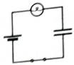
A capacitor is connected to a battery, bulb, and switch as shown. Assume that the switch has been closed for an extended period of time.
1. Predict whether the brightness of the bulb is the same as, greater than, or less than the brightness of a single bulb connected to a battery. Explain.
2. Predict how the potential difference across the battery to the potential differences across the capacitor plates and to the potential difference across the bulb. Explain.
3. Briefly describe the distribution of charge, if any, on the capacitor plates.
Recall the relationship between the charge on a capacitor and the potential difference across the capacitor. Use this relationship to describe how you could use a voltmeter to determine the charge on a capacitor.
4. Obtain the circuit and a voltmeter. Check your predictions for parts 1 and 2.
(1)
To Explain:Whether the brightness of the bulb is the same as, greater than or less than the brightness of a single bulb connected to a battery.
Answer to Problem 1aT
Brightness of the bulb changes with the time in RC circuit but it is constant in case of battery only.
Explanation of Solution
Introduction:
Ohm’s Law: The current in the circuit is directly proportional to the potential difference and the constant of proportionality is known as resistance R.
The potential difference across the capacitor is given as:
Where,
A RC circuit with a battery connected to the capacitor through a Bulb with a resistance of
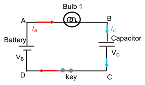
Figure 1: A RC circuit with a battery, bulb and a capacitor
After a long time, the circuit will behave as an open circuit and Therefore, current in the circuit drops to zero with the time till the capacitor voltage equals to the battery voltage.During initial moment, the brightness of the bulb in this RC is equivalent to the single bulb with the battery.But as the time passes, current starts dropping, hence, brightness decreases till the circuit becomes open due to the charging of the capacitor.
Conclusion:
Brightness of the bulb changes with the time in RC circuit but it is constant in case of battery only.
(2)
To Compare: The potential difference across capacitor, bulb and battery.
Answer to Problem 1aT
The voltage difference between the terminals of the battery is
Explanation of Solution
Introduction:
Ohm’s Law: The current in the circuit is directly proportional to the potential difference and the constant of proportionality is known as resistance R.
The potential difference across the capacitor is given as:
Where
A RC circuit with a battery connected to the capacitor through a Bulb with a resistance of

Figure 2: A RC circuit with a battery, bulb and a capacitor
The voltage difference between the terminals of the battery is
Hence, the voltage through the loop can be written as:
Conclusion:
The voltage difference between the terminals of the battery is
(3)
Charge distribution on the plates of the capacitor.
Answer to Problem 1aT
One of the plates accumulates positive and other negative charge in equal magnitude.
Explanation of Solution
Introduction:
The charge on the capacitor is directly proportional to the potential difference across the capacitor plates,
Where ‘C’ is the constant known as the capacitance which depends on the material and design property of the capacitor.
In given circuit, shown in Figure 3, the positive terminal of the battery is connected with the upper plate of the capacitor and the lower one with negative terminal of the battery.
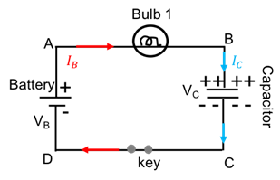
Figure 3: Charge distribution on the capacitor
Current flows from positive terminal of the battery to towards the bulb. Basically, current is in the opposite direction of the flow of the electrons. Electrons from the upper plate of the capacitor starts moving towards positive terminal of the battery and leaves the upper plate positive and electrons in the lower plate are repelled from the negative terminal of the battery. This accumulation of the charge happens till the potential difference across the plate is equal to the battery voltage. Also, the charge on the plates is equal in magnitude and opposite in charge.
Conclusion:
Hence, one of the plates of the capacitor accumulates positive and other negative charge in equal magnitude.
(4)
To Check: The predictions using voltmeter in the circuit.
Explanation of Solution
Introduction:
Ohm’s Law: The current in the circuit is directly proportional to the potential difference and the constant of proportionality is known as resistance R.
The charge on the capacitor is directly proportional to the potential difference across the capacitor plates,
Where ‘C’ is the constant known as the capacitance which depends on the material and design property of the capacitor.
In given circuit, shown in Figure 4, voltmeters are connected parallel to the battery, bulb and the capacitor in order to observe the potential for each circuit element after capacitor is fully charged. Once the capacitor is fully charged, circuit becomes open circuit and hence, no current flows through the circuit.
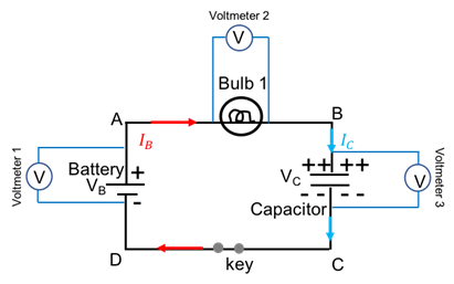
Figure 3: Circuit to calculate Vpotential across battery, bulb and the capacitor
Let say the battery has a
After a long time,the battery voltage is dropped cross the capacitor andpotential across the capacitor is calculated as 5 V and the voltmeter 3 reads 5 V.
Potential across the bulb, and the voltmeter 2 reads 0 V.
Voltmeter 1 reads 5 V.
Charge on the capacitor will be:
Conclusion:
Hence, potential across the battery and the capacitor is 5 V and the bulb is 0 V. Charge on the capacitor is
Want to see more full solutions like this?
Chapter 6 Solutions
Tutorials in Introductory Physics
Additional Science Textbook Solutions
Applied Physics (11th Edition)
Physics for Scientists and Engineers: A Strategic Approach, Vol. 1 (Chs 1-21) (4th Edition)
Life in the Universe (4th Edition)
Physics for Scientists and Engineers with Modern Physics
College Physics: A Strategic Approach (3rd Edition)
Lecture- Tutorials for Introductory Astronomy


- Sketch the diagram for each item and solve what is being asked.1.Three capacitors with individual capacitances of 2 μF, 5 μF, and 10 μF respectively are connected in series with a 12V battery. What are the total capacitance and total charge in the network?arrow_forwardCould you help me to solve the following problem step by step?Thank you very much in advance.5. Discuss the differences between the electric potential and electric field between the conducting and non-conducting sphere, based on the picture. In the picture: Left conducting and right non-conducting.arrow_forwardANSWER BOTH. 1. Define what electric current is with respect to your understanding of the concept of drift velocity. 2.In what ways are electric current and electron flow similar? In what ways are they different from each other? Elaborate your answerarrow_forward
- For each of the capacitors below, calculate the following:(a) The equivalent capacitance for this circuit. (b) The potential drop across each capacitor. (c)Thecharge stored in each capacitor. Here, ?1 = 10 ??, ?2 = 10??, ?3 = 10?? . (Hint: You don’t need to docomplicated math here).a) _______________b) _______________c) _______________arrow_forwardCould you help me to solve the following problem step by step?Thank you very much in advance.6. A) How is capacitance defined? B) To a capacitor with air between its plates with an area of 3 cm2 and a separation between them of 1 mm. If a potential difference of 5 V is applied, calculate a) the electric field generated, b) the surface charge density c) the capacitance d) A dielectric of dielectric constant =3 d) What is the capacitance now?arrow_forwardI am unsure of where I went wrong in my calculations. If possible, please list the steps so I may understand where I went wrong. (a). Ho wmuch charge does a battery have to supply a 5.00 uF capacitor to create a potential difference of 1.20 V across it's plates? (in C) (b). How much energy is stored in the capacitor in this case? (in J) (c). How much charge would the battery have to supply to store 1.50 J of energy in the capacitor? (in C) (d). What would be the potential across the capacitor in that case? (in V)arrow_forward
- Please answer the questions below. The data needed is in the picture. a) If we change the battery into a 5.0V cell, instead of using 1.5V cell, how much energy will be stored in the capacitor? b) If the flash lasts for about 0.001 s, what is the power delivered by the capacitor duringthis brief time? c) If the dielectric used in the capacitor were a 0.010-mm-thick sheet of Strontium titanate (k=234), what would be the surface area of the capacitor plates? Thank you!!arrow_forward1. What is the capacitance between a and b? Show all pertinent solutions. 2. What is the charge on 4µF capacitor if between a and b, there is a batery of 12.0 volts.arrow_forwardA triangular array of resistors is shown in the figure on the right. What current will this array draw from a 35.0V battery having negligible internal resistance if we connect it across a.) ab; b.) bc and c.) ac?arrow_forward
- Consider the circuit configurations below, where two lightbulbs are connected to a single battery in different ways. Based on what you learned about parallel and series connections in lab, which of these two configurations would result in the light bulbs being the brightest? Fully explain your reasoning. Imagine that you are given four 100Ω resistors to build a circuit. Your challenge is to use all four of the resistors in the circuit, but the circuit must have an overall equivalent resistance of 100Ω. Is this possible? If so, draw a diagram of the circuit and explain how the connections result in a 100Ω equivalent resistance. If this is not possible, draw a diagram of a circuit involving all four resistors that has an equivalent resistance as close to 100Ω as is possible.arrow_forwardConsider the example of a parallel combination of capacitors: Three capacitors are connected to each other and to a battery as shown in the figure.(Figure 1) The individual capacitances are C, 2C, and 3C, and the battery's voltage is V. Suppose we consider the system of the three capacitors as a single "equivalent" capacitor. Given the charges of the three individual capacitors calculated in the previous part, find the total charge Qtot for this equivalent capacitor. Express your answer in terms of V and C. Using the value of Qtot, find the equivalent capacitance Ceq for this combination of capacitors. Express your answer in terms of C.arrow_forwardPlease fill out the template below with the work for this problem. Note that you need to have a picture, a list of knowns and unknowns, the general equation/s you will use, and the math steps to solve for the unknown, only plug in the numbers after you have solved for the unknown, and the answer with units included. Question 1: Suppose you have a 195 μF capacitor. What charge is stored in it when 102 V is applied to it, in millicoulombs?arrow_forward
 Glencoe Physics: Principles and Problems, Student...PhysicsISBN:9780078807213Author:Paul W. ZitzewitzPublisher:Glencoe/McGraw-Hill