
Shigley's Mechanical Engineering Design (McGraw-Hill Series in Mechanical Engineering)
10th Edition
ISBN: 9780073398204
Author: Richard G Budynas, Keith J Nisbett
Publisher: McGraw-Hill Education
expand_more
expand_more
format_list_bulleted
Concept explainers
Videos
Textbook Question
Chapter 6, Problem 17P
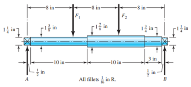
The shaft shown in the figure is machined from AISI 1010 CD steel. The shaft rotates at 1600 rpm and is supported in rolling bearings at A and B. The applied forces are F1 = 2500 Ibf and F2 = 1000 Ibf. Determine the minimum fatigue factor of safety based on achieving infinite life. If infinite life is not predicted, estimate the number of cycles to failure. Also check for yielding.
Problem 6-17
Expert Solution & Answer
Want to see the full answer?
Check out a sample textbook solution
Students have asked these similar questions
The figure shows a shaft mounted in bearings at A and D and having pulleys at B and C. The forces shown acting on the pulley surfaces represent the belt tensions. The shaft is to be made of AISI 1035 CD steel. The shaft is rotating at speed of 1000 rpm. Find the minimum factor of safety for fatigue based on infinite life. If the life is not infinite, estimate the number of cycles. Be sure to check for yielding. Take shaft diameter to be 1.5 inches.
Requlred Informatlon
The shaft shown in the figure is machined from AISI 1040 CD steel. The shaft rotates at 1600 rpm and is supported in
rolling bearings at A and B. The appled forces are F = 900 Ibf and F2 = 1350 Ibf. Determine the minimum fatigue factor of
safety based on achieving infinite life. If infinite life is not predicted, estimate the number of cycles to fallure. Also check
for ylelding.
-8 in-
-8 in-
8 in
F2
17 in
in
3 in
-10 in-
-10 in-
in
글 in
All fillets in R.
B
What are the values of the theoretical stress-concentration factor, the notch sensitivity, and the fatigue stress-concentration factor?
The value of the theoretical stress concentration-factor Is
The value of the notch sensitivity is
The value of the fatigue stress concentration-factor Is
Figure below shows a portion of a pump that is gear-driven at uniform load and speed. The 25 mm diameter solod shaft supported by
the bearings is to be made of machined AISI 1045 CD steel. The helical gear is subjected to the axial force F =499 y a radial
load F = 741 N and a tangential load of F=2,006 N. Assume the component is operating at room temperature of 70°F and the
material has 50% reliability factor.
25-mm solid
Bending K, = 2.0
round shaft Fillet Torsional K = 1.5
F.
F,
Axial K, = 1.8
F
Pump
Helical
spur gear
50 mm
-250-mm dia.-
FIGURE
1. Identify the critical location(s) of stress and show it clearly in a diagram.
2. Identify cleary, all the components of stresses (at the critical point) that will be calculated (by drawing and clearly showing
the XYZ axes) and show it in a matrix form. Show which components of stresses will have a value zero or non-zero.
3. Calculate the principal stresses and principal directions. Show the principal stresses clearly in a stress element…
Chapter 6 Solutions
Shigley's Mechanical Engineering Design (McGraw-Hill Series in Mechanical Engineering)
Ch. 6 - A 10-mm steel drill rod was heat-treated and...Ch. 6 - Prob. 2PCh. 6 - A steel rotating-beam test specimen has an...Ch. 6 - A steel rotating-beam test specimen has an...Ch. 6 - A steel rotating-beam test specimen has an...Ch. 6 - Repeat Prob. 6-5 with the specimen having an...Ch. 6 - A steel rotating-beam test specimen has an...Ch. 6 - Derive Eq. (6-17). Rearrange the equation to solve...Ch. 6 - For the interval 103 N 106 cycles, develop an...Ch. 6 - Estimate the endurance strength of a...
Ch. 6 - Two steels are being considered for manufacture of...Ch. 6 - A 1-in-diamctcr solid round bar has a groove...Ch. 6 - A solid square rod is cantilevered at one end. The...Ch. 6 - A rectangular bar is cut from an AISI 1020...Ch. 6 - A solid round bar with diameter of 2 in has a...Ch. 6 - The rotating shaft shown in the figure is machined...Ch. 6 - The shaft shown in the figure is machined from...Ch. 6 - Solve Prob. 6-17 except with forces F1 = 1200 lbf...Ch. 6 - Bearing reactions R1 and R2 are exerted on the...Ch. 6 - A bar of steel has the minimum properties Se = 40...Ch. 6 - Repeat Prob. 6-20 but with a steady torsional...Ch. 6 - Repeat Prob. 6-20 but with a steady torsional...Ch. 6 - Repeat Prob. 6-20 but with an alternating...Ch. 6 - A bar of steel has the minimum properties Se = 40...Ch. 6 - The cold-drawn AISI KUO steel bar shown in the...Ch. 6 - Repeat Prob. 6-25 for a load that fluctuates from...Ch. 6 - An M14 2 hex-head bolt with a nut is used to...Ch. 6 - The figure shows a formed round-wire cantilever...Ch. 6 - The figure is a drawing of a 4- by 20-mm latching...Ch. 6 - The figure shows the free-body diagram of a...Ch. 6 - Solve Prob. 6-30 except let w1 = 2.5 in. w2 = l.5...Ch. 6 - For the part in Prob. 630, recommend a fillet...Ch. 6 - Prob. 33PCh. 6 - Prob. 34PCh. 6 - A part is loaded with a combination of bending,...Ch. 6 - Repeat the requirements of Prob. 6-35 with the...Ch. 6 - 6-37 to 6-46For the problem specified in the build...Ch. 6 - 6-37 to 6-46For the problem specified in the build...Ch. 6 - 637 to 646 For the problem specified in the table,...Ch. 6 - For the problem specified in the table, build upon...Ch. 6 - 6-37 to 6-46 For the problem specified in the...Ch. 6 - 6-37 to 6-46 For the problem specified in the...Ch. 6 - 6-37 to 6-46 For the problem specified in the...Ch. 6 - Problem Number Original Problem, Page Number 637...Ch. 6 - 6-37 to 6-46 For the problem specified in the...Ch. 6 - 6-37 to 6-46 For the problem specified in the...Ch. 6 - 6-47 to 6-50 For the problem specified in the...Ch. 6 - 6-47 to 6-50 For the problem specified in the...Ch. 6 - Prob. 49PCh. 6 - Prob. 50PCh. 6 - 6-51 to 6-53 For the problem specified in the...Ch. 6 - 6-51 to 6-53 For the problem specified in the...Ch. 6 - 6-51 to 6-53 For the problem specified in the...Ch. 6 - Solve Prob. 6-17 except include a steady torque of...Ch. 6 - Solve Prob. 618 except include a steady torque of...Ch. 6 - In the figure shown, shaft A, made of AISI 1020...Ch. 6 - A schematic of a clutch-testing machine is shown....Ch. 6 - For the clutch of Prob. 657, the external load P...Ch. 6 - A flat leaf spring has fluctuating stress of max =...Ch. 6 - A rotating-beam specimen with an endurance limit...Ch. 6 - A machine part will be cycled at 350 MPa for 5...Ch. 6 - The material properties of a machine part are Sut...Ch. 6 - Repeat Prob. 662 using the Goodman criterion....
Knowledge Booster


Learn more about
Need a deep-dive on the concept behind this application? Look no further. Learn more about this topic, mechanical-engineering and related others by exploring similar questions and additional content below.Similar questions
- a) The rotating step shaft is subjected to the force as shown in the figure. It is supported by bearings at A and F. The shaft is machined using AISI 1040 CD steel. Determine the minimum fatigue factor of safety based on achieving infinite life. If infinite life is not predicted, estimate the number of cycles failure. Also check for yielding. Given Data: (Notch sensitivity (q)=0.8, Sut=85 kpsi, Syield= 71 kpsi, Surface condition modification factor ka=0.879, Size modification factor kb=0.790, Load modification factor kc=1, fatigue fraction (f)=0.867) * In order to determine Kt; Use Figure A-15-9 in your textbook. Dimensions are in inch and all fillet radius:1/14 inch y 860 lbf de 1.75 1.5 1.0 1.0 B V A| D E F 0.5 8 -8.5- R1 R2 -19.5 20arrow_forward5. A non-rotating shaft made of AISI 1018 CD steel is machined to the shape shown below. A load Fy = -250 lbf (pointing down) and F, = F, = 0 lbf is repeatedly applied and removed. Determine the factor of safety for fatigue based on Goodman criterion. If the life is not infinite, estimate the number of cycles to failure (f = 0.9 for S-N curve). 2 in 9 in 1-in dia. B -in R. 2 in 1-in dia. 1글-in dia. -in din. 12 inarrow_forwardThe rotating shaft shown in the figure is machined from AISI 1020 CD steel. It is subjected to a force of F = 6 kN. Find the minimum factor of safety for fatigue based on infinite life. If the life is not infinite, estimate the number of cycles. Be sure to check for yielding. The diameter of the bar is 35 mm and the radius of the step down in the shaft is 3 mm. All dimensions listed below are in mm. 25 D. 20 - 20 -35 D. 180 -3 R. 500- F 280- -175- -50 D. -25 D. -20 20arrow_forward
- Q-3 A 25-mm-diameter solid round bar has a groove 2.5-mm deep with a 2.5-mm radius machined into it. The bar is made of AISI 1050 CD steel and is subjected to a purely reversing torque of 250 N-m. For the S-N curve of this material, let f = 0.9. (a) Estimate the number of cycles to failure. (b) If the bar is also placed in an environment with a temperature of 400°C, estimate the number of cycles to failure.arrow_forwardThe rotating shaft shown in the figure is machined from AISI 1040 CD steel (sy = 490 MPa, Sut = 590 MPa). It is subjected to a transverse force of F = 8 kN between the supports. The system designed to be operated at a temperature of 120°C with a reliability of 99%. Estimate the number of cycles to failure. All dimensions are in mm. Assume all fillets are 3mm in radius. 25 D. 20 20 -35 D. 180- 3 R. 500 F 280 -175- -50 D. 25 D. | ª -20 20arrow_forwardA 1-in-diameter solid round bar has a groove 0.1-in deep with a 0.1-in radius machined into it. The bar is made of AISI 1020 CD steel and is subjected to a purely reversing torque of 1800 lb-in. For the S-N diagram of this material, let f=0.9. Estimate the number of cycles to failure. If the bar is also placed in an environment with a temperature of 750 F, estimate the number of cycles to failurearrow_forward
- Figure below shows a portion of a pump that is gear-driven at uniform load and speed. The 25 mm diameter solod shaft supported by the bearings is to be made of machined AISI 1045 CD steel. The helical gear is subjected to the axial force F-498 y a radial load F- 750 N and a tangential load of F-1.995 N. Assume the component is g at room temperature of 70F and the material has s0s reliability factor. Hint: Be careful when you calculate the bending moment at the fillet, as all the three forces on the helical gear cause bending moment at the fillet. Calculate resultant bedina moment from all the three forces. Bending moment is completely reversed loading.) 25-mm solid round shaft Fillet Bending K, = 2.0 Torsional k, = 1.5 Axial K,18 F. F, F Pump Helical spur gear -50 mm -250-mm dia FIGURE 1. Identify the critical locations) of stress and show it clearly in a diagram. 2 Identity cleary, all the components of stresses (at the critical point) that will be calcurated (by drawing and clearty…arrow_forwardFigure below shows a rotating shaft simply supported in ball bearings at A and D and loaded by a nonrotating orce Fof 6.8 kN. Using ASTM "minimum" strengths, estimate the life of the part. 6T td7 (a) Shaft drawing showing all dimensions in millimeters; all fillets 3-mm radius. The shaft rotates and the load is stationary; material is machined from AISI 1050 cold-drawn steel. (b) Bending moment diagram.arrow_forwardA 20° 20-tooth cast-iron spur pinion having a module of 4 mm drives a 32-tooth cast-iron gear. Find the contact stress if the pinion speed is 1020 rev/min, the face width is 50 mm, and 10 kW of power is transmitted. Refer to table number 14-8 for elastic coefficient. The contact stress is MPa.arrow_forward
- Use the general shaft layout given and determine critical diameters of the shaft based on infinite fatigue life with a design factor of 1.5. Check for yielding. Check the slopes at the bearings for satisfaction of the recommended limits in Table 7-2. Assume that the deflections for the pulleys are not likely to be critical. 10 in 500 lbf 75 lbf 8-in dia. Bearing at O 10.0" 500 lb d 75 lb Material 1040 Q and T 18 in Use the following shaft layout assuming a pulley transmits torque through a key and keyseat at location A to another pulley at location B. Assume the tensions in the belt at pulley Bare T₁ and T2, where T₁ is 15% of T2. NOTE: This is a multi-part question. Once an answer is submitted, you will be unable to return to this part. 10-in dia. 12 in T₂ 8.0⁰ T₁ 18.0" 10.0" I B pulley diameter = 8.0" Sut 113 kpsi T2 T1 pulley diameter = 10.0" Sy 86 kpsi 12.0" Bearing at C Using the DE-Goodman criteria and a design factor of 1.5, calculate the diameter based on the shaft's loadings…arrow_forwardUse the general shaft layout given and determine critical diameters of the shaft based on infinite fatigue life with a design factor of 1.5. Check for yielding. Check the slopes at the bearings for satisfaction of the recommended limits in Table 7-2. Assume that the deflections for the pulleys are not likely to be critical. 500 lbf 75 lbf 8-in dia. Bearing at O 500 lb d 10.0" 75 lb Material 1040 Q and T 18 in Use the following shaft layout assuming a pulley transmits torque through a key and keyseat at location A to another pulley at location B. Assume the tensions in the belt at pulley B are T₁ and T2, where T₁ is 15% of T2. NOTE: This is a multi-part question. Once an answer is submitted, you will be unable to return to this part. 10-in dia. 12 in T₂ T₁ The mean torque is 0 lb-in. The alternating torque is 2125 lb-in. The mean moment is 0 lb-in. The alternating moment is 5000 lb-in. 18.0" pulley diameter = 8.0" Sut 113 kpsi 10.0 B T2 T1 pulley diameter = 10.0" Sy 86 kpsi 12.0"…arrow_forwardThe shaft shown in the figure is machined from AISI 1040 CD steel. The shaft rotates at 1600 rpm and is supported in rolling bearings at A and B. The applied forces are F1 = 1600 lbf and F2 = 640 lbf. A steady torque of 1600 lbf·in is being transmitted through the shaft between the points of application of the forces.arrow_forward
arrow_back_ios
SEE MORE QUESTIONS
arrow_forward_ios
Recommended textbooks for you
 Elements Of ElectromagneticsMechanical EngineeringISBN:9780190698614Author:Sadiku, Matthew N. O.Publisher:Oxford University Press
 Mechanics of Materials (10th Edition)Mechanical EngineeringISBN:9780134319650Author:Russell C. HibbelerPublisher:PEARSON
 Thermodynamics: An Engineering ApproachMechanical EngineeringISBN:9781259822674Author:Yunus A. Cengel Dr., Michael A. BolesPublisher:McGraw-Hill Education
 Control Systems EngineeringMechanical EngineeringISBN:9781118170519Author:Norman S. NisePublisher:WILEY
 Mechanics of Materials (MindTap Course List)Mechanical EngineeringISBN:9781337093347Author:Barry J. Goodno, James M. GerePublisher:Cengage Learning
 Engineering Mechanics: StaticsMechanical EngineeringISBN:9781118807330Author:James L. Meriam, L. G. Kraige, J. N. BoltonPublisher:WILEY
Elements Of Electromagnetics
Mechanical Engineering
ISBN:9780190698614
Author:Sadiku, Matthew N. O.
Publisher:Oxford University Press
Mechanics of Materials (10th Edition)
Mechanical Engineering
ISBN:9780134319650
Author:Russell C. Hibbeler
Publisher:PEARSON
Thermodynamics: An Engineering Approach
Mechanical Engineering
ISBN:9781259822674
Author:Yunus A. Cengel Dr., Michael A. Boles
Publisher:McGraw-Hill Education
Control Systems Engineering
Mechanical Engineering
ISBN:9781118170519
Author:Norman S. Nise
Publisher:WILEY
Mechanics of Materials (MindTap Course List)
Mechanical Engineering
ISBN:9781337093347
Author:Barry J. Goodno, James M. Gere
Publisher:Cengage Learning
Engineering Mechanics: Statics
Mechanical Engineering
ISBN:9781118807330
Author:James L. Meriam, L. G. Kraige, J. N. Bolton
Publisher:WILEY
Everything About COMBINED LOADING in 10 Minutes! Mechanics of Materials; Author: Less Boring Lectures;https://www.youtube.com/watch?v=N-PlI900hSg;License: Standard youtube license